canon manual 7d

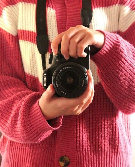
The Canon EOS 7D is a high-performance DSLR camera designed for professionals and enthusiasts, offering advanced features like weather resistance, 19-point autofocus, and full HD video capabilities․

1․1 Overview of the Canon EOS 7D

The Canon EOS 7D is an 18-megapixel DSLR camera featuring a high-resolution APS-C CMOS sensor, dual DIGIC 4 processors, and a weather-sealed magnesium alloy body․ It offers 8 fps continuous shooting, Full HD video recording, and a 19-point cross-type autofocus system․ Designed for professionals and enthusiasts, it combines durability with advanced imaging capabilities for both stills and video․

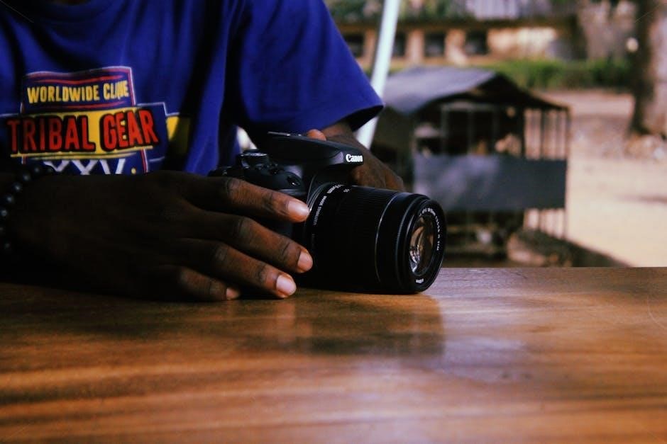
1․2 Key Features of the Canon EOS 7D

The EOS 7D boasts an 18․0 MP CMOS sensor, dual DIGIC 4 processors, and ISO 12800 expandability․ It offers 8 fps continuous shooting, 19-point cross-type AF, and full HD video recording with manual controls․ Weather-sealed, magnesium alloy construction ensures durability, while advanced metering modes, customizable functions, and compatibility with EF-S lenses enhance versatility for photographers seeking high performance․

1․3 Importance of the Canon EOS 7D Manual

The EOS 7D manual is essential for unlocking the camera’s full potential, providing detailed explanations of its features and settings․ It guides users in mastering advanced functions, customizing controls, and optimizing performance for various photography scenarios․ This comprehensive resource ensures photographers maximize their creative control and achieve professional results with confidence and precision․

Canon EOS 7D vs․ EOS 7D Mark II

The EOS 7D Mark II offers enhanced features, including a 20․2MP sensor, 65-point AF, and dual-pixel autofocus, surpassing the original 7D’s capabilities for improved performance․

2․1 Differences in Specifications

The EOS 7D Mark II boasts a 20․2MP CMOS sensor, dual DIGIC 5 processors, and 65 cross-type AF points, while the original 7D features an 18MP sensor, dual DIGIC 4 processors, and 19 cross-type AF points․ The Mark II also offers an expanded ISO range (100-16000) and faster continuous shooting (10 fps vs․ 8 fps), making it more powerful for professional photographers․

2․2 Upgrades and Improvements in the Mark II

The EOS 7D Mark II features a 20․2MP CMOS sensor, dual DIGIC 5 processors, and 65 cross-type AF points for enhanced performance․ It offers an expanded ISO range (100-16000) and faster continuous shooting (10 fps)․ The Mark II also includes improved weather sealing, a more durable shutter (200,000 cycles), and enhanced video capabilities with manual exposure control, making it a significant upgrade for professionals․

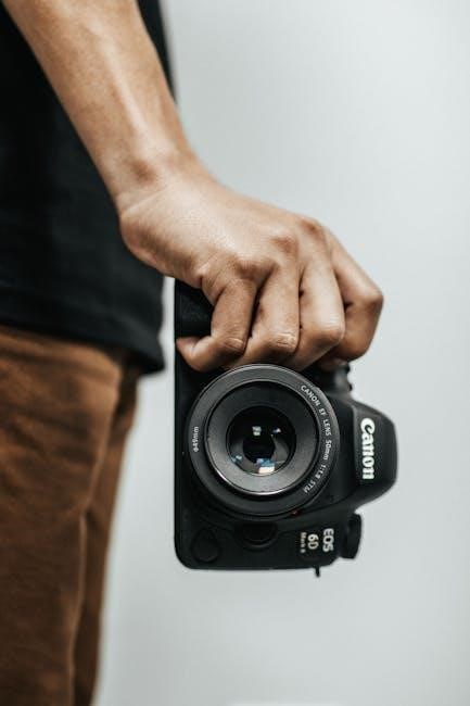
Camera Build and Design

The Canon EOS 7D boasts a magnesium alloy body, ensuring durability and weather resistance, perfect for challenging environments․ Its ergonomic design provides a comfortable grip and intuitive controls․

3․1 Durability and Weather Resistance

The Canon EOS 7D features a robust magnesium alloy body, offering exceptional durability and resistance to dust and moisture․ Its weather-sealed construction ensures reliable performance in harsh conditions, making it ideal for outdoor and professional photography․ This build quality, combined with a shutter durability of up to 150,000 cycles, ensures long-lasting reliability for photographers․

3․2 Ergonomics and User-Friendly Interface

The Canon EOS 7D boasts an ergonomic design with intuitive controls, ensuring comfortable handling during extended shoots․ Customizable buttons and a logical layout simplify access to key functions․ The camera’s user-friendly interface, including the Quick Control Dial and Intelligent Viewfinder, enhances workflow efficiency, making it adaptable to various shooting styles and preferences for photographers of all levels․

Autofocus and Metering Systems

The Canon EOS 7D features a 19-point cross-type autofocus system for precise subject tracking and a 63-zone metering system for accurate exposure control, ensuring sharp and balanced images․

4․1 19-Point Cross-Type Autofocus System

The Canon EOS 7D’s 19-point cross-type autofocus system ensures precise and rapid subject tracking, even for fast-moving objects․ It utilizes AI Servo II technology for predictive focus tracking and features a dedicated AF processor for enhanced performance․ This advanced system provides reliable focus acquisition in various lighting conditions, making it ideal for sports, wildlife, and action photography․

4․2 Metering Modes for Accurate Exposure

The Canon EOS 7D offers four metering modes: Evaluative, Center-Weighted, Partial, and Spot․ Evaluative metering uses 63 zones and links to the autofocus system for precise exposure․ Center-Weighted emphasizes the center for portraits, while Partial and Spot metering allow precise control over specific areas․ This system ensures accurate exposure in various lighting conditions, delivering consistent results․

Shooting Modes and Customization

The Canon EOS 7D offers versatile shooting modes, including Auto, P, Tv, Av, and M, allowing photographers to customize settings for personalized control and creative freedom․

5․1 Understanding Auto, P, Tv, Av, and M Modes

The Canon EOS 7D offers several shooting modes for photographers: Auto for point-and-shoot simplicity, P (Program AE) for automatic settings with customization, Tv (Shutter Priority) to control shutter speed, Av (Aperture Priority) to adjust aperture, and M (Manual) for full control over both․ Each mode provides flexibility, catering to different skill levels and creative needs effortlessly․

5․2 Custom Functions for Personalized Shooting

The Canon EOS 7D allows photographers to tailor their shooting experience through customizable functions․ Users can adjust settings like autofocus tracking, metering modes, and button assignments to suit their preferences․ These custom functions enhance control and productivity, enabling photographers to optimize the camera for their specific needs and shooting styles․

Video Capabilities and Manual Controls

The Canon EOS 7D offers Full HD video recording at 30p, 24p, and 25p with manual exposure control, audio adjustments, and selectable ISO settings․

6․1 Full HD Video Recording Features

The Canon EOS 7D captures stunning Full HD video at 30p, 24p, and 25p frame rates, offering cinematic quality and flexibility․ With manual exposure control, users can adjust settings like aperture, shutter speed, and ISO during recording for precise creative control․ The camera also supports selectable frame rates, enabling filmmakers to achieve various artistic effects and professional-grade video output․

6․2 Manual Exposure and Audio Controls

The Canon EOS 7D offers manual exposure controls during video recording, allowing users to adjust aperture, shutter speed, and ISO for tailored results․ Additionally, it features manual audio level adjustment, enabling precise sound capture․ These controls enhance creative freedom, making the 7D a versatile tool for both photographers and videographers seeking professional-grade output in various shooting scenarios and conditions․

ISO Range and Noise Performance

Canon EOS 7D offers an ISO range of 100-12800, delivering excellent low-light performance․ It effectively manages noise at higher settings, ensuring high-quality results in various conditions․

7․1 ISO Sensitivity for Low-Light Photography

The Canon EOS 7D features an ISO range of 100-12800, expandable to 12800, making it ideal for low-light photography․ Dual DIGIC 4 processors optimize noise reduction, ensuring sharp, detailed images even in challenging lighting conditions․ This capability allows photographers to capture high-quality shots without excessive noise, making it versatile for both professional and enthusiast use․

7․2 Managing Noise at High ISO Settings

The EOS 7D effectively manages noise at high ISOs using its dual DIGIC 4 processors, which optimize image processing and minimize grain․ While noise increases at ISO 6400 and above, it remains manageable for most applications․ For best results, use noise reduction tools in post-processing or enable in-camera noise reduction for cleaner images in low-light conditions․

Continuous Shooting and Buffer Capacity

The EOS 7D delivers high-speed continuous shooting at 8 fps, making it ideal for action photography․ Its buffer capacity allows for extended bursts, optimizing workflow efficiency․

8․1 High-Speed Continuous Shooting (8 fps)

The Canon EOS 7D offers impressive high-speed continuous shooting at 8 frames per second, making it ideal for capturing dynamic action sequences and fast-moving subjects․ This feature is particularly beneficial for sports and wildlife photography, allowing photographers to freeze fleeting moments with precision․ The camera’s buffer capacity supports extended bursts, ensuring uninterrupted shooting sessions․ Using fast memory cards and optimizing file formats like RAW or JPEG can further enhance performance․

8․2 Optimizing Buffer Performance

To maximize the Canon EOS 7D’s buffer capacity, use high-speed memory cards and adjust file formats․ Shooting in JPEG increases burst capacity compared to RAW․ Reducing file sizes via settings like ISO sensitivity and smaller RAW options also helps․ Regularly updating firmware ensures optimal performance․ Balancing these factors allows for extended continuous shooting sessions, making it ideal for capturing sequential action shots efficiently․

Menu System and Navigation

The Canon EOS 7D features a user-friendly menu system with tab-based navigation, allowing quick access to shooting, playback, and setup options․ Customizable My Menu and registered settings enhance efficiency․

9․1 Navigating the Canon EOS 7D Menu

The Canon EOS 7D menu system is intuitive, with tab-based navigation for easy access to shooting, playback, and setup options․ Users can scroll through tabs using the Quick Control Dial, selecting options with the SET button․ The menu also features customization options, such as My Menu, allowing users to register frequently used settings for quick access․ This streamlined design enhances workflow efficiency․

9․2 Customizing the Menu for Efficiency

The Canon EOS 7D allows users to customize the menu system for streamlined workflows․ By registering frequently used settings in the My Menu tab, photographers can quickly access their most-used options․ Additionally, custom functions enable assignment of specific features to camera buttons, optimizing personal shooting preferences․ This customization enhances efficiency and tailors the camera to individual workflows․

Accessories and Compatibility

The Canon EOS 7D is compatible with EF-S lenses, including the EF-S 15-85mm and EF-S 10-22mm, and supports external flash units for enhanced photography versatility․

10․1 Recommended Lenses for the EOS 7D

The Canon EOS 7D pairs well with EF-S lenses like the EF-S 15-85mm f/3․5-5․6 IS USM and EF-S 10-22mm f/3․5-4․5 USM for wide-angle shots․ The EF 70-200mm f/4L USM is ideal for telephoto needs, offering sharp images and reliable performance․ These lenses, along with external flashes, enhance the camera’s versatility for various photography styles and lighting conditions․

10․2 External Flash and Other Accessories

For enhanced lighting control, the Canon EOS 7D supports external flashes like the Speedlite 580EX II, offering advanced flash metering and wireless capabilities․ Additional accessories include the Battery Grip BG-E7 for extended shooting and improved ergonomics, as well as remote shutter releases and high-capacity memory cards for seamless photography sessions․

Troubleshooting Common Issues

The Canon EOS 7D may encounter issues like autofocus errors or unexpected shut downs․ Regular firmware updates and resetting the camera often resolve these problems․ Consulting the manual and Canon’s support resources can provide detailed troubleshooting steps․

11․1 Resolving Autofocus and Metering Problems

Autofocus issues can often be resolved by cleaning the sensor and lens․ Metering problems may require adjusting settings or calibrating lenses․ Ensure firmware is updated and settings are reset․ Using the correct AF mode for the scene and checking metering patterns in the manual can help․ Contact Canon support if problems persist for professional assistance․

11․2 Fixing Error Messages and Firmware Updates

Common error messages can often be resolved by resetting the camera or updating firmware․ Visit the Canon website for the latest firmware version and follow installation instructions using EOS Utility․ Ensure no interruptions during updates to avoid damage․ Updated firmware enhances performance and fixes bugs․ If issues persist, refer to the manual or contact Canon support for assistance․

The Canon EOS 7D is a powerful tool for photographers, offering exceptional performance and customization․ To maximize its potential, explore manual settings and stay updated with firmware improvements․

12․1 Recap of the Canon EOS 7D’s Strengths

The Canon EOS 7D is a high-performance DSLR designed for professionals and enthusiasts․ It features an 18MP CMOS sensor, dual DIGIC 4 processors, and captures images with impressive speed and clarity․ With 8 fps continuous shooting and a 19-point cross-type AF system, it excels in dynamic photography․ Its weather-sealed body and full HD video capabilities make it versatile and reliable for various shooting conditions․ This camera is a testament to Canon’s commitment to quality and performance․

12․2 Tips for Getting the Most Out of Your Camera

To maximize your Canon EOS 7D’s potential, familiarize yourself with its manual and explore custom settings․ Experiment with shooting modes like Manual, Av, and Tv for creative control; Regularly update firmware and clean the sensor for optimal performance․ Practice various techniques and review your photos to refine your skills․ Explore its video capabilities for versatile storytelling․

volvo penta workshop manual pdf

The Volvo Penta Workshop Manual is a comprehensive guide designed for service workshops and qualified personnel, providing detailed technical specifications, repair procedures, and essential maintenance protocols for Volvo Penta engines.

1.1 Overview of the Volvo Penta Workshop Manual

The Volvo Penta Workshop Manual is a detailed resource covering technical specifications, repair procedures, and maintenance guidelines for Volvo Penta engines. Designed for professionals and DIY enthusiasts, it includes diagrams, troubleshooting tips, and safety precautions. The manual supports various engine models, such as MD2010, MD2020, and D1-13, ensuring comprehensive coverage. Regular updates keep the content relevant, making it an essential tool for efficient and accurate servicing of Volvo Penta marine engines.

1.2 Importance of the Manual for Service Workshops

The Volvo Penta Workshop Manual is indispensable for service workshops, offering standardized procedures and model-specific repair instructions. It ensures adherence to safety protocols and proper diagnostic techniques, minimizing errors and downtime. By providing detailed technical data and troubleshooting guides, the manual empowers workshops to deliver efficient and accurate servicing. Its accessibility via PDF further enhances convenience, making it a cost-effective and reliable resource for professionals maintaining Volvo Penta engines. Regular updates ensure alignment with the latest engineering advancements.

Key Features of the Volvo Penta Workshop Manual

The Volvo Penta Workshop Manual includes detailed technical specifications, repair instructions, safety guidelines, and diagrams. It also features a search function for quick reference and model-specific information.

2.1 Technical Specifications and Descriptions

The Volvo Penta Workshop Manual provides detailed technical specifications and descriptions for various engine models, including part numbers, torque specifications, and operational parameters. It offers clear explanations of engine components, electrical systems, and mechanical assemblies. Diagrams and illustrations are included to enhance understanding of complex systems. This section is essential for diagnosing and repairing issues, ensuring accuracy and compliance with manufacturer standards. It also covers model-specific information, such as the MD2010, MD2020, and MD2030 engines, making it a vital resource for professionals and DIY enthusiasts.

2.2 Repair Instructions and Procedures

The Volvo Penta Workshop Manual includes detailed repair instructions and procedures for various engine components, ensuring precise and efficient servicing. Step-by-step guides cover everything from routine maintenance to complex overhauls, supported by diagrams and illustrations. Special tools and techniques are highlighted to facilitate accurate repairs. This section is designed to help professionals and DIY enthusiasts alike perform tasks safely and effectively, adhering to Volvo Penta’s high standards. It emphasizes the importance of following proper sequences to avoid damage and ensure reliability.

2.3 Safety Guidelines and Precautions

The Volvo Penta Workshop Manual emphasizes safety guidelines and precautions to ensure secure servicing and repair operations. It highlights the importance of avoiding contact between harness terminals and contaminants like oil or water. Proper use of protective equipment and adherence to electrical and mechanical safety practices are stressed. Users are advised to follow specific protocols when handling connectors and to consult relevant sections for engine-specific safety measures. These guidelines are crucial for preventing accidents and maintaining the integrity of the engine and surrounding systems.

How to Use the Volvo Penta Workshop Manual Effectively

The Volvo Penta Workshop Manual is designed for easy navigation, featuring a detailed table of contents and search functionality to quickly locate specific repair procedures and guidelines.

3.1 Navigating the Table of Contents

The Volvo Penta Workshop Manual features a logically organized table of contents, allowing users to quickly locate specific sections. It includes categories like Technical Specifications, Repair Procedures, and Maintenance Schedules, ensuring easy access to essential information. The manual is structured to guide users through diagnostic processes, troubleshooting, and detailed repair instructions. By familiarizing yourself with the table of contents, you can efficiently navigate and find the exact information needed for your task. This setup enhances productivity for both professionals and DIY enthusiasts.

3.2 Understanding Diagrams and Illustrations

The Volvo Penta Workshop Manual includes detailed diagrams and illustrations to assist with complex repairs and maintenance tasks. These visuals provide clear, step-by-step guidance, making it easier to understand component locations and assembly processes. From wiring diagrams to exploded views of engine parts, the manual ensures that users can identify and address issues accurately. The diagrams are complemented by descriptive text, offering a comprehensive resource for both professional mechanics and DIY enthusiasts to work efficiently and safely.

3.3 Essential Tools and Equipment Required

The Volvo Penta Workshop Manual outlines the essential tools and equipment needed for effective repairs and maintenance. Specialized tools, such as torque wrenches and multimeters, are required for precise adjustments and diagnostics. Basic tools like screwdrivers, pliers, and wrenches are also necessary for disassembly and assembly tasks. Additionally, the manual emphasizes the importance of using genuine Volvo Penta parts and recommended lubricants to ensure optimal performance and longevity of the engine. Safety equipment, such as gloves and protective eyewear, is also recommended for safe working practices.

Engine-Specific Information in the Manual

The Volvo Penta Workshop Manual provides detailed engine-specific information, including technical specifications, repair procedures, and diagnostics for various engine models like MD2010, MD2020, and MD2030.

4.1 Common Engine Types Covered

The Volvo Penta Workshop Manual covers a wide range of engine types, including MD2010, MD2020, MD2030, MD2040, and D1-13, D1-20, D1-30, D2-40. These engines are popular in marine applications, offering both diesel and gasoline options. The manual provides detailed specifications, repair procedures, and troubleshooting guides for each model, ensuring comprehensive coverage for maintenance and service work. Whether for pleasure boats or commercial vessels, the manual supports engines ranging from 10 to 1,000 hp, making it an invaluable resource for professionals and DIY enthusiasts.

4.2 Model-Specific Repair Instructions

The Volvo Penta Workshop Manual provides detailed, model-specific repair instructions for engines like the D1-13, D1-20, D1-30, D2-40, and MD22. Each section offers step-by-step guides tailored to the unique features of the engine, ensuring accurate and efficient repairs. The manual includes troubleshooting tips, torque specifications, and diagrams specific to each model. This ensures that technicians and enthusiasts can address issues confidently, adhering to Volvo Penta’s standards for quality and safety. The instructions cover everything from basic maintenance to complex overhauls.

4.3 Diagnostic Procedures and Troubleshooting

The Volvo Penta Workshop Manual includes detailed diagnostic procedures and troubleshooting guides to help identify and resolve engine issues efficiently. It provides step-by-step instructions for checking fault codes, testing systems, and repairing common faults. The manual also features troubleshooting charts and maintenance schedules to ensure optimal engine performance. By following these procedures, users can quickly pinpoint problems, such as engine starting issues or cooling system malfunctions, and apply the correct fixes. This section is essential for both professional mechanics and DIY enthusiasts.

Maintenance and Service Protocols

The Volvo Penta Workshop Manual provides a comprehensive guide for regular maintenance and service protocols, ensuring optimal engine performance and longevity. It includes detailed schedules for oil changes, cooling system checks, and other essential tasks to keep your engine in prime condition.

5.1 Regular Maintenance Schedule

The Volvo Penta Workshop Manual outlines a detailed regular maintenance schedule to ensure optimal engine performance and longevity. It includes tasks such as oil and filter changes, coolant inspections, and belt replacements, all tailored to specific engine models. The manual recommends checking anodes, impellers, and fuel systems at regular intervals to prevent corrosion and wear. By following this schedule, users can avoid costly repairs and maintain their engine’s efficiency. Always refer to the manual for model-specific guidelines and frequency recommendations. Regular maintenance ensures reliability and extends the lifespan of your Volvo Penta engine.

5.2 Oil and Filter Change Procedures

The Volvo Penta Workshop Manual provides detailed oil and filter change procedures to ensure proper engine lubrication and performance. It specifies the recommended oil types and filter replacements for different engine models. The manual outlines step-by-step instructions for draining old oil, replacing the oil filter, and refilling with new oil. Regular oil changes are crucial for maintaining engine longevity and preventing wear. Always use genuine Volvo Penta parts to ensure compatibility and optimal performance. Dispose of used oil and filters responsibly to protect the environment. Refer to the manual for model-specific guidelines.

5.3 Cooling System and Thermostat Maintenance

The Volvo Penta Workshop Manual emphasizes the importance of regular cooling system maintenance to prevent overheating and ensure optimal engine performance. It provides detailed instructions for checking coolant levels, inspecting hoses, and flushing the system. Additionally, the manual outlines procedures for replacing the thermostat and ensuring proper torque specifications. Regular maintenance helps maintain engine efficiency and prevents damage from corrosion or debris buildup. Always follow the manual’s guidelines for model-specific cooling system requirements and use genuine Volvo Penta parts for reliability.

Advantages of the Volvo Penta Workshop Manual PDF

The Volvo Penta Workshop Manual PDF offers unmatched accessibility, allowing users to access critical repair and maintenance information anytime, anywhere. Its search functionality enables quick reference, while its digital format ensures cost-effective DIY repairs and environmental sustainability.

6.1 Accessibility and Convenience

The Volvo Penta Workshop Manual PDF provides unparalleled accessibility and convenience, allowing users to access critical information from any device, including computers, tablets, and smartphones. Its portable digital format eliminates the need for physical storage, enabling easy transport and retrieval. The PDF can be quickly downloaded from the Volvo Penta Connect platform, ensuring users always have the latest version. This digital accessibility is especially valuable for remote workshops and DIY enthusiasts, offering instant access to repair guides and technical data without delays.

6.2 Search Functionality for Quick Reference

The Volvo Penta Workshop Manual PDF features advanced search functionality, enabling users to quickly locate specific topics, models, or procedures. This tool is invaluable for professionals and DIY enthusiasts, saving time by eliminating the need to manually navigate through hundreds of pages. With a few keystrokes, users can access detailed repair instructions, technical specifications, and troubleshooting charts. This feature enhances efficiency and ensures that critical information is readily available, making the manual an indispensable resource for marine engine maintenance and repair.

6.3 Cost-Effective Solution for DIY Repairs

The Volvo Penta Workshop Manual PDF serves as a cost-effective solution for DIY enthusiasts, offering detailed repair instructions, troubleshooting guides, and maintenance protocols. By providing access to comprehensive technical data, it empowers users to perform repairs independently, reducing reliance on professional services. The manual’s clear instructions and diagrams help minimize errors, saving time and money. This resource is particularly valuable for boat owners who want to maintain their engines efficiently without incurring high service costs.

Tips for Professionals and DIY Enthusiasts

This section offers practical advice for both experienced mechanics and DIYers, ensuring efficient and safe repairs. Professionals are encouraged to use specialized tools and stay updated on the latest manual revisions, while DIY enthusiasts should follow step-by-step instructions carefully to avoid errors. Regular maintenance and proper troubleshooting techniques are emphasized for all users.

7.1 Recommendations for Professional Mechanics

Professional mechanics should prioritize using specialized tools and adhering to the manual’s guidelines for precise repairs. Regularly updating with the latest manual revisions ensures compliance with current standards. Conducting thorough diagnostics before starting repairs is crucial, and performing function tests after completion guarantees optimal performance. Adhering to safety protocols and maintaining a clean workspace minimizes risks. Leveraging the manual’s detailed diagrams and troubleshooting sections can enhance efficiency and accuracy in service work. Staying updated and following these practices ensures reliable outcomes for Volvo Penta engines.

7.2 Guidance for DIY Boat Owners

The Volvo Penta Workshop Manual PDF is a valuable resource for DIY boat owners, offering clear instructions for routine maintenance and repairs. It is essential to follow the manual’s step-by-step guides and safety precautions to avoid damage or injury. DIY enthusiasts should focus on regular maintenance tasks such as oil changes, cooling system checks, and filter replacements. For complex issues, consulting the troubleshooting section or seeking professional assistance is recommended. Always use the correct tools and adhere to the manual’s guidelines to ensure safety and effectiveness.

7.3 Staying Updated with the Latest Revisions

To ensure optimal performance and compliance with the latest standards, it is crucial to stay updated with the most recent revisions of the Volvo Penta Workshop Manual PDF. Regularly check the official Volvo Penta website or the Volvo Penta Connect platform for updates. These revisions often include new technical specifications, improved repair procedures, and enhanced safety guidelines. By staying informed, users can access the latest diagnostic tools and troubleshooting methods, ensuring their engine operates efficiently and safely. Always refer to the most current version for accurate and reliable information.

The Volvo Penta Workshop Manual PDF is an indispensable resource for professionals and DIY enthusiasts alike, offering detailed guidance for engine maintenance, repair, and troubleshooting. Its comprehensive coverage ensures users can handle complex tasks with confidence. By adhering to the manual’s instructions, users can maintain their engines’ peak performance, safety, and longevity. Regular updates and revisions further enhance its value, making it a trusted companion for anyone working with Volvo Penta marine engines. Always rely on the latest version for optimal results.

brother hl 2270dw user manual

Welcome to the Brother HL-2270DW user manual, your essential guide to understanding the printer’s features, setup, and maintenance. This manual ensures optimal performance and troubleshooting for all users.

1.1 Overview of the Printer and Its Features

The Brother HL-2270DW is a compact laser printer designed for high-efficiency printing. It offers wireless and wired connectivity, a print resolution of up to 2400 x 600 dpi, and a print speed of up to 27 ppm. Features include automatic duplex printing, a 250-sheet paper tray, and compatibility with mobile printing solutions. It supports both Windows and macOS systems, ensuring versatile performance for home and office use.

1.2 Importance of Reading the Manual for Optimal Performance

Reading the Brother HL-2270DW user manual is crucial for unlocking its full potential. It provides detailed guidance on installation, configuration, and troubleshooting, ensuring smooth operation. Understanding the manual helps users maximize print quality, resolve common issues, and utilize advanced features effectively, enhancing overall productivity and efficiency.

Key Features and Technical Specifications

The Brother HL-2270DW is a compact laser printer offering 2400 x 600 dpi resolution, 27 ppm print speed, wireless and wired connectivity, and a 250-sheet paper capacity, ensuring efficient performance.

2.1 Print Resolution and Speed

The Brother HL-2270DW delivers crisp text with a print resolution of up to 2400 x 600 dpi and prints at speeds of up to 27 pages per minute, making it ideal for fast and high-quality monochrome printing needs in home or office environments.

2.2 Connectivity Options (Wired and Wireless)

The Brother HL-2270DW offers versatile connectivity options, including a built-in Ethernet interface for wired networks and wireless 802.11b/g/n for seamless integration with mobile devices; It supports AirPrint, Google Cloud Print, and Brother’s iPrint&Scan app, enabling effortless printing from smartphones and tablets without the need for cables.

2.3 Paper Handling and Capacity

The Brother HL-2270DW features a 250-sheet standard paper tray and a manual feed slot for envelopes or specialty paper. It supports various paper sizes, including letter, A4, legal, and executive formats. The printer also includes an output tray that holds up to 100 sheets, ensuring efficient printing for both small and medium-sized workloads.

2.4 Compatibility with Operating Systems

The Brother HL-2270DW is compatible with Windows, macOS, and Linux operating systems, ensuring versatility across different platforms. It supports Windows 10, 8.1, 8, 7, macOS 10.15 or later, and various Linux distributions. Drivers and software are available for seamless installation, making it easy to integrate the printer into your existing workflow. Wireless and network compatibility further enhance its adaptability for diverse computing environments.

Installation and Setup Guide

This section provides a step-by-step guide to installing and setting up your Brother HL-2270DW printer. It covers unboxing, connecting the printer, installing drivers, and initial configuration to ensure smooth operation.

3.1 Unboxing and Physical Setup

Start by carefully unpacking the Brother HL-2270DW printer from its box. Ensure all accessories, including the power cord, toner cartridge, and installation CD, are included. Place the printer on a flat, stable surface away from direct sunlight and moisture. Remove any protective packaging materials and plastic covers. Connect the power cord and install the toner cartridge as instructed. This prepares your printer for initial power-on and setup.

3.2 Software Installation for Windows and macOS

Install the Brother HL-2270DW printer software using the provided CD or by downloading the latest drivers from Brother’s official website. For Windows, run the installer and follow on-screen instructions to select your connection type (USB or network). On macOS, use the Add Printer utility in System Preferences to locate and install the printer. Ensure the printer is connected to the same network for wireless setups.

3.3 Initial Configuration and Calibration

After installation, power on the printer and set your preferred language, time, and unit settings. Configure network settings for wired or wireless connections. Calibrate the printer by aligning the print heads and ensuring proper paper handling. Perform a test print to verify print quality and alignment. Regular calibration ensures accurate prints and prevents paper jams or misalignments.

Network Configuration

Configure wired or wireless connections, adjust settings via BRAdmin Light utility or web interface, enable security features like encryption and access controls, and troubleshoot connectivity issues with diagnostic tools and guidelines.

4.1 Wired Network Setup

Connect the printer to your network using an Ethernet cable. Use the BRAdmin Light utility for initial setup, configuring IP addresses, and subnet masks. Access the printer’s web interface via its IP address to manage advanced settings. Ensure the printer is recognized by your network and test connectivity. Troubleshoot issues by checking physical connections and network settings. Refer to the manual for detailed configuration steps and support.

4.2 Wireless Network Configuration

Configure the Brother HL-2270DW for wireless printing using the Brother installer from the CD-ROM or Wi-Fi Protected Setup (WPS). Select your network name (SSID), enter the password, and follow on-screen instructions. For manual setup, enable wireless mode and input network settings. Ensure your router supports 802.11b/g standards. Refer to the manual for troubleshooting wireless connectivity issues and optimizing network performance.

4.3 Troubleshooting Network Connectivity Issues

Resolve wireless or wired network issues by checking cable connections and ensuring the printer is on the same network as your devices. Restart the printer and router, then print a network configuration report. Use BRAdmin Light utility to diagnose IP address conflicts or signal strength problems. Consult the manual for detailed steps to restore connectivity and ensure seamless printing operations.

Using the Printer

Welcome to the section on using your Brother HL-2270DW printer. Here, you’ll learn how to perform essential tasks such as printing, scanning, and copying with ease and efficiency.

5.1 Basic Printing Operations

Learn how to perform basic printing tasks with your Brother HL-2270DW. This section covers selecting print settings, choosing paper trays, print quality options, and using eco-mode for toner-saving prints.

5.2 Advanced Printing Features

Explore advanced printing options like duplex printing, toner-saving modes, and custom print quality settings. Use the Toner Save Mode to reduce toner consumption. Adjust print resolution for specific needs. Utilize the Eco Mode for energy-efficient printing. Access these features through the printer driver or control panel for enhanced printing flexibility and efficiency.

5.3 Scanning and Copying Functions

The Brother HL-2270DW supports scanning and copying with ease. Use the flatbed scanner for high-quality scans up to 600×600 dpi. Copy documents with options for reduction, enlargement, or fit-to-page; ID Copy feature allows copying both sides of a document onto a single sheet. Multiple copy modes are available, with a maximum of 99 copies. Ensure sharp and clear reproductions every time.

Maintenance and Troubleshooting

Regular maintenance ensures optimal performance. Clean the printer and replace toner and drum units as needed. Troubleshoot common issues like paper jams or connectivity problems promptly to minimize downtime.

6.1 Common Printer Issues and Solutions

  • Paper Jams: Turn off the printer, carefully remove jammed paper, and ensure proper alignment of paper trays.
  • Toner Issues: Check toner levels, replace cartridges when low, and clean the corona wire for optimal print quality.
  • Connectivity Problems: Restart the printer and router, ensure network settings are correct, and reinstall drivers if necessary.
  • Error Messages: Refer to the manual or online support for specific solutions, often resolved by resetting the printer.

6.2 Cleaning and Maintaining the Printer

Regular maintenance ensures optimal performance. Turn off the printer, clean the exterior with a soft cloth, and gently remove dust from internal parts using compressed air. Check and replace worn pick-up rollers. Update firmware periodically for improved functionality. Clean the corona wire to prevent print defects. Use genuine Brother supplies and schedule professional servicing if needed.

6.3 Replacing Toner and Drum Units

Turn off the printer and open the front cover. Remove the toner cartridge and drum unit assembly. Take out the old toner cartridge, then install the new one. Reattach the drum unit and close the cover. Align the drum unit if necessary. Regular replacement ensures high-quality prints. Always use genuine Brother supplies for optimal performance and longevity of your printer.

Security Features

The Brother HL-2270DW includes advanced security features such as network encryption and secure data protection to safeguard your printing environment. These features ensure confidential documents remain protected.

7.1 Network Security Settings

The Brother HL-2270DW offers robust network security settings, including encryption protocols and secure data transmission. Users can configure firewalls, enable secure authentication, and set up access controls to protect the printer from unauthorized access. These features ensure safe communication over both wired and wireless connections, safeguarding sensitive information and maintaining network integrity.

7.2 Data Protection and Encryption

The Brother HL-2270DW employs advanced encryption protocols, such as SSL/TLS and IPsec, to secure data transmission. These features protect sensitive information from unauthorized access, ensuring confidentiality and integrity during printing and scanning operations. Encryption safeguards data both in transit and at rest, providing an additional layer of security for your documents and network communication.

Advanced Features

The Brother HL-2270DW offers mobile printing via AirPrint and Google Cloud Print, enabling seamless wireless connectivity. Additionally, it supports web-based management for remote printer configuration and monitoring, enhancing productivity and convenience for users.

8.1 Mobile Printing Options

The Brother HL-2270DW supports mobile printing through AirPrint for iOS devices and Google Cloud Print for Android and Chrome OS. Users can print documents and photos wirelessly from their smartphones or tablets. Additionally, the Brother iPrint&Scan app allows direct printing and scanning from mobile devices, ensuring convenience and productivity on the go.

8.2 Cloud Printing and Connectivity

The Brother HL-2270DW enables seamless cloud printing through services like Google Cloud Print, allowing users to print documents from anywhere with internet access. It supports secure wireless connections and integrates with popular cloud platforms. The printer also features robust encryption for data protection. For optimal cloud connectivity, ensure your printer is updated with the latest firmware and drivers, available through the Brother Solutions Center.

Environmental and Safety Considerations

The Brother HL-2270DW is designed with energy efficiency in mind, featuring power-saving modes to reduce energy consumption. Always follow safety precautions to avoid potential hazards and ensure proper usage.

9.1 Energy Efficiency and Power Saving Modes

The Brother HL-2270DW incorporates energy-efficient technologies to minimize power consumption. It features an automatic sleep mode that activates when the printer is inactive, reducing energy use. Additionally, the printer supports toner-saving modes, which lower toner consumption during draft printing. These eco-friendly features help reduce operational costs and environmental impact, aligning with green printing initiatives. Proper use of these modes ensures optimal energy efficiency.

9.2 Safety Precautions and Warnings

Ensure safe operation by following precautions: avoid overheating sources, keep toner away from children, and prevent physical contact with internal components. Use approved power cords and avoid overloading circuits. Handle cartridges carefully to prevent spills. Follow proper startup and shutdown procedures to avoid damage. Regular maintenance and adherence to guidelines ensure user safety and optimal printer performance. Always unplug during maintenance.

10.1 Final Tips for Maximizing Printer Performance

Regularly maintain your printer by cleaning and updating firmware. Use genuine Brother supplies for optimal output. Enable energy-saving modes to reduce power consumption. Ensure proper paper alignment and adjust settings for specific print jobs. Consult the manual for advanced features and troubleshooting. Proper care ensures longevity and peak performance of your Brother HL-2270DW printer.

acura mdx 2016 owners manual

Welcome to the Acura MDX 2016 Owners Manual, your comprehensive guide to understanding and maintaining your vehicle․ This manual provides essential information to help you operate and care for your SUV effectively․

Inside, you’ll find detailed sections on safety features, vehicle maintenance, advanced technology, and troubleshooting․ The manual is designed to ensure your driving experience is safe and enjoyable․

Whether you’re familiar with Acura vehicles or new to the brand, this guide will help you make the most of your MDX․ Explore its features, learn proper maintenance practices, and discover how to utilize its advanced systems․

For your convenience, the manual is available online as a downloadable PDF, making it easy to access anytime․ Refer to it regularly to keep your Acura MDX in optimal condition․

1․1 Purpose and Structure of the Manual

The Acura MDX 2016 Owners Manual is designed to provide clear, concise information to help owners understand and maintain their vehicle effectively․ It is structured to guide users through safety precautions, vehicle features, maintenance schedules, and troubleshooting․ The manual is divided into logical sections, ensuring easy navigation and quick access to essential information․ Key topics include interior and exterior components, advanced technology systems, and warranty details․ This comprehensive guide is intended to enhance the driving experience while ensuring proper care and maintenance of the Acura MDX․

By following the manual, owners can optimize performance, safety, and longevity of their vehicle․ The structured format makes it easy to locate specific details, from routine maintenance to advanced features․ Whether you’re a new or experienced owner, this manual serves as an invaluable resource for all aspects of Acura MDX ownership․

1․2 Table of Contents and Navigation

The Acura MDX 2016 Owners Manual features a detailed table of contents, making it easy to navigate and locate specific information․ Organized into logical sections, the manual covers topics such as safety precautions, vehicle features, maintenance schedules, and troubleshooting․ Each section is clearly labeled and subdivided for quick access, ensuring users can find what they need efficiently․ The table of contents serves as a roadmap, guiding owners through the manual’s extensive resources․ With clear headings and concise descriptions, the manual is designed to enhance user experience and provide seamless navigation․

Safety Precautions and Guidelines

The Acura MDX 2016 Owners Manual emphasizes safety as a top priority․ Key sections include proper seatbelt usage, airbag functionality, and child restraint guidelines․ Warning lights and emergency procedures are also detailed to ensure driver and passenger safety․ Adhering to these guidelines helps protect occupants and prevents potential damage to the vehicle․ Always refer to this section for critical safety information before operating your MDX․

2․1 General Safety Information

The Acura MDX 2016 Owners Manual provides essential safety guidelines to ensure a secure driving experience․ Seatbelts are a critical component, and proper usage is emphasized to minimize injury risk․ The manual also details airbag locations and precautions to avoid obstruction․ Child restraints are addressed, with instructions for correct installation in the second-row seats․ Additionally, warning lights and indicators are explained to alert drivers of potential issues․ Adhering to these guidelines is crucial for maintaining vehicle integrity and occupant safety․ Always review this section before operating your MDX to ensure safe driving practices․

2․2 Safety Features of the Acura MDX 2016

The 2016 Acura MDX is equipped with an array of advanced safety features designed to protect occupants and prevent accidents․ Collision Mitigation Braking and Adaptive Cruise Control enhance driver assistance, while Lane Departure Warning and Lane-Keeping Assist help maintain road positioning․ The Multi-View Rear Camera provides clear visibility when reversing, and Vehicle Stability Assist ensures traction control․ These features, combined with a robust structural design, create a safer driving environment․ Understanding and utilizing these technologies can significantly enhance your safety on the road․

2․3 Proper Use of Safety Equipment

Proper use of safety equipment is crucial for maximizing protection in your Acura MDX 2016․ Always wear seatbelts correctly, ensuring they are securely fastened for all occupants․ The airbag system is designed to deploy in conjunction with seatbelts, so never modify or disable it․ Familiarize yourself with the Multi-View Rear Camera to safely navigate while reversing․ Avoid relying solely on technology; always check surroundings manually․ If equipped, the Homelink system requires proper setup to function correctly․ For resetting codes or retraining buttons, refer to the manual․ Understanding and correctly using these features enhances safety and driving confidence․

Vehicle Features and Controls

The Acura MDX 2016 boasts advanced features like a Multi-View Rear Camera, customizable controls, and an intuitive infotainment system․ Explore interior and exterior components designed for comfort and functionality, ensuring a seamless driving experience․

3․1 Interior Features and Components

The Acura MDX 2016 interior is designed for luxury and functionality․ Key features include heated and ventilated front seats, a dual-screen infotainment system, and a premium audio setup․ The cabin offers ample space, with seating for up to seven passengers and versatile cargo configurations․ Controls for climate, audio, and navigation are ergonomically placed, ensuring ease of use while driving․ The interior also features advanced technology such as the Multi-Information Display and voice command functions, enhancing both convenience and connectivity․ These components work together to create a comfortable and tech-savvy environment for all occupants․

3․2 Exterior Features and Components

The Acura MDX 2016 boasts a sleek and aerodynamic exterior design, featuring Jewel Eye LED headlights, a chrome grille, and a power tailgate for convenience․ The vehicle is equipped with 19-inch aluminum alloy wheels, providing both style and durability․ Exterior components include roof rails, a rear spoiler, and LED taillights, enhancing both functionality and visual appeal․ The MDX also offers an optional panoramic moonroof, allowing natural light to illuminate the cabin․ These features are designed to balance aesthetic appeal with practicality, ensuring a premium and modern look while maintaining robust performance capabilities․

3․3 Advanced Technology and Infotainment Systems

The Acura MDX 2016 features a sophisticated infotainment system designed to enhance your driving experience․ The centerpiece is an intuitive touchscreen interface, offering navigation, audio controls, and connectivity options․ Voice command functionality allows hands-free operation, while Bluetooth and USB ports ensure seamless smartphone integration․ The system supports Apple CarPlay and Android Auto, enabling access to your favorite apps․ Additional features include a premium audio system with surround sound and a rear entertainment system for passengers․ These advanced technologies provide convenience, entertainment, and connectivity, making every journey enjoyable and stress-free․

Maintenance and Service Schedule

Regular maintenance is crucial for optimal performance and longevity of your Acura MDX․ Follow the recommended schedule for oil changes, tire rotations, and inspections․ Refer to the manual for detailed service intervals to ensure reliability and safety․

4․1 Recommended Maintenance Schedule

Regular maintenance is essential to ensure your Acura MDX 2016 runs efficiently and safely․ The recommended schedule includes oil changes every 5,000 to 7,500 miles, tire rotations every 7,500 miles, and brake inspections every 15,000 miles․ Additionally, the manual advises checking and replacing the air filter every 15,000 to 30,000 miles and the spark plugs every 105,000 miles․ Proper timing belt replacement is also crucial, typically recommended at 105,000 miles․ Following this schedule helps maintain performance, prevent costly repairs, and ensures your vehicle remains under warranty․ Refer to the manual for a detailed breakdown of service intervals and procedures․

4․2 DIY Maintenance Tips

Performing routine maintenance yourself can save time and money․ Start by checking oil levels regularly and topping them off as needed․ Tire pressure should be inspected monthly and adjusted to the recommended levels found in your manual․ Air filters can be cleaned or replaced at home, improving fuel efficiency and performance․ Additionally, windshield washer fluid should be refilled regularly, and wiper blades replaced when showing signs of wear․ Always refer to your manual for guidance before starting any DIY task․ Use genuine Acura parts to ensure compatibility and maintain your vehicle’s performance․ Remember to keep a record of all maintenance for future reference․

4․3 Service Log and Record-Keeping

Maintaining a detailed service log is crucial for tracking your Acura MDX’s maintenance history․ Record every service, including oil changes, tire rotations, and part replacements, with dates and mileages․ This log helps ensure warranty claims are processed smoothly and provides proof of proper vehicle care․ Use the manual’s service schedule as a guide and note any additional repairs or inspections․ Store receipts and invoices for parts and labor in a secure location․ Regular record-keeping not only helps avoid service overlaps but also enhances resale value by demonstrating responsible ownership․ Keep your log organized and updated for optimal vehicle maintenance․

Troubleshooting Common Issues

This section guides you through identifying and resolving common problems with your Acura MDX․ Learn how to diagnose issues, check error codes, and consult the manual for solutions․ If problems persist, contact an authorized Acura dealer for professional assistance․

5․1 Identifying and Addressing Common Problems

Your Acura MDX 2016 Owners Manual provides guidance on diagnosing and resolving common issues․ Familiarize yourself with dashboard warning lights and error codes, as they indicate specific problems․ For example, the HomeLink button may need retraining if it stops working․ Refer to the manual for step-by-step solutions and reset procedures․ If issues persist, consult an authorized Acura service center for professional assistance; Regularly reviewing this section helps ensure your vehicle operates at peak performance and prevents minor problems from becoming major concerns․

  • Check error codes using the instrument cluster or OBD-II scanner․
  • Reset codes or retrain systems as instructed in the manual․
  • Address issues promptly to avoid further complications․

5․2 Resetting Codes and Retraining Systems

The Acura MDX 2016 Owners Manual outlines procedures for resetting codes and retraining systems․ After resolving issues, use the manual’s guidance to clear error codes via the instrument cluster or OBD-II scanner․ For features like HomeLink, retraining may be necessary if functionality is lost․ Refer to the manual for step-by-step instructions to reset systems and restore proper operation․ Ensure all procedures are followed carefully to avoid system malfunctions․ If unsure, consult an Acura specialist for assistance․ Regular system checks and resets help maintain your vehicle’s performance and reliability․

  • Use the OBD-II scanner to clear trouble codes after repairs․
  • Retrain systems like HomeLink following battery disconnections or fob replacements․
  • Consult the manual or Acura’s website for detailed reset procedures․

Warranty Information

Understand your Acura MDX 2016 warranty coverage, including terms, conditions, and what is covered․ Find details on tires, accessories, and replacement parts in the manual or online․

6․1 Coverage and Terms of the Acura Warranty

The Acura MDX 2016 warranty provides comprehensive coverage for parts and labor, ensuring your vehicle is protected against defects in materials and workmanship․ The warranty includes:

  • New Vehicle Limited Warranty: Covers repairs for 3 years or 36,000 miles․
  • Powertrain Limited Warranty: Extends coverage for 5 years or 60,000 miles․
  • Rust Perforation Warranty: Protects against rust-through for 5 years regardless of mileage․

Certain exclusions apply, such as maintenance items and accessories․ The warranty is valid for the original purchaser and is non-transferable․ Refer to the manual for full details or visit owners․acura․com for more information․

6․2 Accessories, Replacement Parts, and Warranty

This section outlines the warranty coverage for Acura-approved accessories and replacement parts․ Genuine Acura accessories installed at the time of purchase are covered under the New Vehicle Limited Warranty for 3 years or 36,000 miles․ Replacement parts purchased from authorized Acura dealers are also covered, with specific terms varying by component․ Non-genuine parts may not be covered under the warranty․ For details on what is included and excluded, refer to the warranty section or contact an Acura representative․ Always use Acura-approved parts to ensure warranty compliance and maintain your vehicle’s performance․ Visit owners․acura․com for more information․

Appendices

The appendices provide technical specifications, conversion charts, and a glossary of terms․ These sections offer quick references and clarify complex terminologies to help owners understand their vehicle better․

7․1 Technical Specifications

The technical specifications section details the Acura MDX 2016’s key components, including engine type, transmission, horsepower, and fuel capacity․ It also outlines dimensions, suspension, and braking systems, providing a comprehensive overview of the vehicle’s performance capabilities․ This section is essential for understanding the mechanical aspects and ensuring proper maintenance․ Whether troubleshooting or planning modifications, this data serves as a reliable reference for owners seeking precise technical information about their SUV․

7․2 Conversion Charts and Units of Measurement

This section provides essential conversion charts and units of measurement to help owners understand various technical specifications․ It includes conversions between metric and imperial systems, such as kilometers to miles, liters to gallons, and kilograms to pounds․ Additionally, it covers units for pressure, temperature, and torque, ensuring clarity for maintenance and repair tasks․ These charts are invaluable for interpreting data like tire pressure, engine oil capacity, and fuel efficiency․ They also assist in troubleshooting by standardizing measurements, making it easier to follow instructions and ensure accuracy when working on the vehicle․

7․3 Glossary of Terms

The glossary of terms provides clear definitions for technical and automotive terminology used throughout the manual․ It helps owners understand complex terms related to vehicle systems, maintenance, and safety features․ This section is particularly useful for new owners or those unfamiliar with automotive jargon․ Terms are alphabetically organized for easy reference, covering topics like engine specifications, safety technologies, and infotainment systems․ The glossary ensures that all users can interpret instructions accurately, enhancing their understanding of the vehicle’s operation and maintenance․ It serves as a quick reference guide to decode technical language, making the manual more accessible and user-friendly․

russell evaporator manual

This manual provides a comprehensive guide for installing‚ operating‚ and maintaining Russell evaporators‚ ensuring optimal performance and safety in refrigeration systems. It includes troubleshooting tips and maintenance schedules.

1.1 Overview of Russell Refrigeration Systems

Russell Refrigeration Systems offer high-efficiency solutions for commercial applications‚ including unit coolers‚ condensing units‚ and packaged systems. Designed for walk-in coolers‚ freezers‚ and warehouses‚ these systems provide reliable temperature control with options for air‚ electric‚ and hot gas defrost models‚ ensuring optimal performance across various industries.

1.2 Importance of Proper Installation and Maintenance

Proper installation and maintenance are crucial for ensuring efficient operation‚ safety‚ and longevity of Russell evaporators. Correct placement and setup prevent performance issues‚ while regular cleaning and inspections maintain optimal cooling; Adhering to guidelines ensures reliable operation‚ reduces energy costs‚ and minimizes downtime‚ ultimately extending the system’s lifespan and ensuring consistent refrigeration performance across various applications.

Installation and Mounting Guidelines

Proper location‚ mounting‚ and piping ensure optimal evaporator performance. Follow guidelines for airflow‚ clearance‚ and connections to maximize efficiency and maintain reliable refrigeration system operation.

2.1 Locating Walk-In Evaporators for Optimal Air Circulation

Locate evaporators to ensure unobstructed airflow‚ covering the entire room. Avoid placing near doors or restricting inlet/outlet streams. Direct air toward doors or aisles for even distribution. Maintain clearance for service and circulation‚ ensuring efficient cooling and system performance.

2.2 Mounting and Placement Considerations

Ensure evaporators are securely mounted on sturdy structures to avoid vibration. Maintain clearance from walls and obstacles for proper airflow and service access. Position units away from doors to prevent air circulation interference. Verify the drain pan is correctly aligned and accessible. Check unit levelness to ensure proper operation. Follow manufacturer guidelines for specific mounting requirements to optimize performance and longevity.

2.3 Piping and Connections

Proper piping installation is critical for efficient evaporator performance. Ensure correct line sizing to avoid pressure drops. Use insulated piping for suction and discharge lines to minimize heat loss. Verify all connections are leak-free and securely fastened. Follow the manual’s guidelines for piping layouts to ensure compliance with design specifications and optimal system operation.

Maintenance and Inspection

Regular maintenance is essential for optimal performance and longevity. Inspect evaporator coils‚ fans‚ and drain pans for cleanliness and damage; Schedule periodic cleaning and ensure proper airflow for efficient operation.

3.1 Cleaning Evaporator Coils and Guards

Regularly clean evaporator coils and guards to maintain efficiency and prevent damage. Use non-corrosive cleaners to remove dirt and grease. Ensure all electrical power is disconnected before cleaning. Avoid using ammonia or abrasive materials that could harm the coils. Proper cleaning ensures optimal airflow and prevents system malfunctions‚ extending the lifespan of the evaporator.

3.2 Regular Maintenance Schedules

Adhere to a routine maintenance schedule to ensure the evaporator operates efficiently. Inspect coils‚ fans‚ and defrost systems monthly. Clean components as needed and replace worn parts promptly. Schedule professional checks annually to address hidden issues. Regular maintenance prevents unexpected breakdowns‚ reduces energy costs‚ and extends the evaporator’s lifespan‚ ensuring reliable performance in refrigeration systems.

Troubleshooting Common Issues

Identify symptoms like reduced airflow‚ frosting‚ or temperature fluctuations. Check wiring diagrams‚ defrost cycles‚ and pressure readings to diagnose problems. Refer to the manual for solutions.

4.1 Diagnosing Evaporator Performance Problems

Identify evaporator performance issues by checking temperature fluctuations‚ frosting‚ or reduced airflow. Measure suction line temperatures and pressures‚ using conversion charts to diagnose root causes. Ensure proper defrost cycles and airflow patterns. Inspect for blockages or misalignments in air streams; Refer to the manual for detailed troubleshooting steps and solutions to optimize performance.

4.2 Addressing Common Faults and Errors

Common faults include malfunctioning defrost systems‚ clogged drain pans‚ and improper superheat settings. Reset or replace faulty sensors‚ clean debris from coils‚ and adjust temperature controls as needed. Refer to wiring diagrams for electrical issues. Follow manual guidelines to resolve errors promptly‚ ensuring efficient operation and extending equipment lifespan. Regular maintenance prevents recurring problems.

Defrosting and Temperature Control

Proper defrosting ensures efficient evaporator operation‚ while temperature control maintains optimal cooling. Air‚ electric‚ or hot gas defrost systems are options‚ with adjustable settings for precise management.

5.1 Understanding Defrost Cycles

Defrost cycles are crucial for maintaining evaporator efficiency by removing ice buildup. Russell systems offer air‚ electric‚ or hot gas defrost options. The cycle typically involves temporarily stopping refrigeration to allow ice to melt‚ ensuring optimal airflow and heat exchange. Proper defrost cycle management prevents performance issues and extends equipment lifespan‚ ensuring consistent cooling performance in refrigeration systems.

5.2 Managing Evaporator Temperature Settings

Managing evaporator temperature settings ensures efficient operation. Russell evaporators allow precise adjustments to meet specific cooling needs. Proper temperature control prevents excessive energy use and maintains product quality. The system terminates defrost cycles based on set temperatures‚ optimizing performance and longevity. Regular monitoring ensures settings align with operational requirements‚ maximizing energy efficiency and system reliability.

Calculating Evaporator Superheat

Measure suction line temperature and pressure‚ then use conversion charts to determine superheat. This ensures proper refrigeration system performance and prevents potential operational issues.

6.1 Step-by-Step Guide to Measuring Superheat

Measure the suction line temperature at the expansion valve using an electronic thermometer. 2. Obtain the suction pressure reading at the evaporator connection. 3. Convert the pressure to temperature using a conversion chart. 4. Subtract the converted temperature from the measured suction line temperature to determine superheat. This ensures accurate system performance and prevents operational issues.

6.2 Using Temperature/Pressure Conversion Charts

Temperature/pressure conversion charts are essential for determining refrigerant temperature from pressure readings. Locate the pressure value on the chart and align it with the corresponding temperature. This process helps verify evaporator performance and calculate superheat accurately. Regularly refer to these charts during maintenance to ensure system efficiency and prevent issues like icing or overloading.

Air Circulation and Performance Optimization

Ensure proper air circulation by positioning evaporators to avoid airflow restrictions. Optimal placement enhances cooling efficiency and prevents performance issues. Maintain clearance for servicing and airflow direction.

7.1 Ensuring Proper Airflow in Walk-In Coolers

Proper airflow is critical for optimal cooling performance. Evaporators should be positioned to ensure unrestricted airflow‚ avoiding obstructions near inlet/outlet streams. Direct airflow toward doors or aisles for even distribution. Maintain sufficient clearance between units and walls for servicing and air circulation. Poor airflow can lead to uneven cooling and increased energy consumption‚ emphasizing the need for strategic placement and maintenance.

7.2 Avoiding Restrictions in Inlet/Outlet Air Streams

Russell evaporators require unobstructed inlet and outlet air streams for efficient operation. Avoid placing units near doors or walls‚ as this can disrupt airflow. Ensure no objects block the paths‚ and maintain recommended clearances. Restrictions can reduce cooling efficiency‚ increase energy costs‚ and strain the system‚ leading to potential malfunctions. Proper placement ensures balanced air circulation and optimal performance.

Product Specifications and Models

Russell offers a range of evaporator models‚ including Slim-Temp and All-Temp‚ designed for energy efficiency. These models serve various applications in commercial refrigeration‚ ensuring optimal performance.

8.1 Overview of Russell Unit Coolers

Russell unit coolers are designed for versatility and efficiency‚ suitable for walk-in coolers‚ freezers‚ and warehouses. They feature air‚ electric‚ and hot gas defrost options‚ ensuring optimal performance across various applications. These units are built with durable materials and advanced technology to meet the demands of commercial refrigeration systems‚ providing reliable cooling solutions.

8.2 Key Features of Slim-Temp and All-Temp Models

Slim-Temp and All-Temp models by Russell offer advanced airflow designs‚ low-profile configurations‚ and energy-efficient operation. Slim-Temp models excel in space-saving applications‚ while All-Temp units provide universal performance for diverse environments. Both feature durable construction‚ easy maintenance‚ and precise temperature control‚ making them ideal for commercial refrigeration needs‚ including coolers‚ freezers‚ and warehouses.

Safety Precautions and Best Practices

Always disconnect power before servicing. Use non-corrosive cleaners for coils. Follow proper handling guidelines to avoid damage and ensure safe operation of Russell evaporator systems.

9.1 Handling and Safety Guidelines

Ensure all electrical power is disconnected before inspection or maintenance. Use protective equipment like gloves and goggles. Avoid corrosive cleaners that may damage copper or aluminum components. Regularly inspect evaporator coils and guards for dirt or grease buildup. Follow manufacturer guidelines for handling and transporting units to prevent structural damage. Maintain a clean and stable work environment during servicing.

9.2 Emergency Procedures and Shutdown

In case of emergencies‚ immediately disconnect the main power supply and close the liquid and suction valves. Vent the system to relieve pressure. Activate the emergency stop button if available. Refer to the wiring diagram in the evaporator’s end panel for specific shutdown procedures. Always follow safety protocols to ensure safe system isolation and prevent accidental startups.

Wiring Diagrams and Electrical Connections

Wiring diagrams for Russell evaporators are located in the unit’s end panel‚ detailing connections for defrost models. Follow manufacturer guidelines for safe electrical installations and connections.

10.1 Understanding Evaporator Wiring Schemes

Evaporator wiring schemes are detailed in the unit’s end panel‚ providing clear connections for defrost models. Hot gas‚ electric‚ and air defrost systems have specific wiring configurations. Ensure all electrical connections match the recommended voltage and horsepower ratings for safe and efficient operation.

10.2 Typical Wiring Diagrams for Defrost Models

Typical wiring diagrams for defrost models are located in the evaporator’s end panel‚ detailing connections for hot gas‚ electric‚ and air defrost systems. These diagrams provide clear guidance on component wiring‚ including defrost sensors‚ fan motors‚ and control circuits. Always follow the manufacturer’s guidelines for proper installation and troubleshooting to ensure safe and efficient operation of the defrost system.

Common Issues and Solutions

Common issues include frosting problems‚ sensor malfunctions‚ and drainage blockages. Solutions involve adjusting defrost settings‚ cleaning sensors‚ and ensuring proper drainage to maintain efficiency and performance.

11.1 Addressing Frequent Operational Problems

Frequent issues include frosting problems‚ sensor malfunctions‚ and drainage blockages. Solutions involve adjusting defrost settings‚ cleaning sensors‚ and ensuring proper drainage. Regularly inspect and clean evaporator coils to prevent efficiency loss. Check wiring for loose connections and verify fluid levels. Addressing these problems promptly ensures smooth operation and extends the lifespan of the evaporator system.

11.2 Tips for Extending Evaporator Lifespan

Regular lubrication of fan motors and proper alignment of components prevent wear. Clean air filters to ensure optimal airflow. Monitor operating pressures and temperatures to avoid overload. Schedule professional inspections annually. Replace worn seals promptly to prevent leaks. Maintain a dry environment to reduce corrosion. These practices enhance efficiency and prolong the evaporator’s operational lifespan significantly.

siemens hydroranger 200 manual

The Siemens HydroRanger 200 is an advanced ultrasonic level controller designed for water and wastewater management, offering reliable measurement solutions for tanks, hoppers, and bunkers.

Overview of the HydroRanger 200 System

The Siemens HydroRanger 200 is a robust ultrasonic level controller designed for continuous measurement in water and wastewater storage tanks, hoppers, and bunkers. Part of the Siemens Milltronics series, it ensures accurate and reliable level monitoring. Its non-contact technology suits harsh environments, while its compatibility with solids, liquids, and slurries makes it versatile for industrial applications. The system integrates seamlessly with control systems, enabling efficient monitoring and operation.

Importance of the Manual for Effective Operation

The manual is essential for understanding and optimizing the Siemens HydroRanger 200’s functionality. It provides detailed instructions for installation, configuration, and troubleshooting, ensuring proper setup and operation. The manual also outlines safety guidelines, maintenance routines, and advanced features, enabling users to maximize performance and compliance with industry standards. Referencing the manual ensures accurate configuration and troubleshooting, critical for reliable level measurement in water and wastewater applications.

Key Features of the Siemens HydroRanger 200

The Siemens HydroRanger 200 features ultrasonic level measurement, ideal for water and wastewater applications. It supports control of up to six pumps and measures levels up to 15 meters accurately.

Ultrasonic Level Measurement Technology

The Siemens HydroRanger 200 utilizes advanced ultrasonic level measurement technology, providing accurate and reliable detection of liquid, slurry, and solid levels. This non-contact method ensures minimal maintenance and eliminates wear from moving parts. It operates effectively in various environments, including water storage tanks, wastewater treatment facilities, and industrial hoppers. The technology offers consistent performance across fluctuating conditions, making it a robust solution for diverse applications.

Applications in Water and Wastewater Management

The Siemens HydroRanger 200 is widely used in water and wastewater management for measuring levels in storage tanks, treatment plants, and pumping stations. Its versatility allows it to handle liquids of varying consistencies, from clean water to slurries and solids. The device supports pump control, differential measurement, and flow monitoring, making it an essential tool for ensuring efficient and reliable operations in municipal and industrial water systems.

Technical Specifications of the HydroRanger 200

The HydroRanger 200 offers precise ultrasonic level measurement, supporting depths up to 15 meters and compatible with various liquids and solids, ensuring reliable performance in diverse applications.

Measurement Range and Accuracy

The Siemens HydroRanger 200 delivers exceptional accuracy with a measurement range of up to 15 meters, ensuring precise level detection in various liquids and slurries. Its advanced ultrasonic technology minimizes errors, providing reliable data for consistent process control. The device supports diverse applications, from water storage tanks to industrial bunkers, with tailored settings to optimize performance in each environment. This ensures accurate and dependable measurements, critical for efficient operations.

Compatibility with Various Liquids and Solids

The Siemens HydroRanger 200 is designed for compatibility with a wide range of liquids, slurries, and solids. It effectively measures levels in water, wastewater, and industrial applications like hoppers and bunkers. The device supports various transducer options, ensuring optimal performance across different mediums. This versatility makes it a reliable solution for diverse operational needs, enhancing efficiency in multiple industries.

Installation and Setup of the HydroRanger 200

Proper installation ensures optimal performance. Follow manual guidelines for preparation, mounting, and wiring to guarantee accurate level measurement and reliable operation.

Preparation and Mounting Requirements

Proper preparation and mounting are critical for the HydroRanger 200. Ensure the device is installed in a suitable location, away from interference. Use twisted, shielded copper wire for wiring, and route cables in grounded metal conduit. Follow manual guidelines for panel mounting and ensure all connections are secure. Proper transport, storage, and installation practices must be observed to maintain performance and compliance with safety standards.

Wiring and Connection Guidelines

For the Siemens HydroRanger 200, use 2-core copper wire, twisted and shielded, for expansions up to 365 meters (1200 feet). Route cables in grounded metal conduit, separate from other cables. Properly connect white and black wires with the screen to avoid interference. Ensure compliance with safety standards during installation and operation.

Operating the HydroRanger 200

The Siemens HydroRanger 200 operates using ultrasonic technology to measure levels, controlling up to six pumps for water and wastewater management with high accuracy and reliability.

Basic Principles of Operation

The Siemens HydroRanger 200 operates using ultrasonic waves to measure liquid or solid levels. It emits sound pulses, which bounce off the surface and return as echoes. The device processes these echoes to calculate distance and level. This non-contact method ensures accuracy and reliability, with a typical measurement range of up to 15 meters. It is ideal for water, wastewater, and industrial applications, providing continuous monitoring and control with minimal maintenance required.

Programming and Configuration Options

The HydroRanger 200 offers flexible programming options, allowing users to customize settings for specific applications. Configuration is done via an intuitive HMI, enabling easy setup of measurement parameters, relay controls, and pump management. The device supports multiple measurement modes, including level, volume, and flow calculation. Advanced features like data logging and communication interfaces ensure seamless integration into industrial systems, making it adaptable for diverse operational needs.

Troubleshooting and Maintenance

The HydroRanger 200 requires regular maintenance to ensure optimal performance. Common issues include sensor contamination and wiring faults. Troubleshooting involves checking connections and cleaning sensors. Scheduled maintenance includes software updates and verifying calibration accuracy to prevent measurement errors and ensure reliable operation.

Common Issues and Solutions

Common issues with the HydroRanger 200 include faulty connections, sensor contamination, and software glitches. Solutions involve checking wiring integrity, cleaning the sensor, and updating firmware. Regular calibration ensures accuracy, while resetting default settings can resolve configuration errors. Proper grounding and shielding of cables prevent interference. Consulting the manual or contacting Siemens support is recommended for persistent problems, ensuring optimal performance and reliability in level measurement applications.

Regular Maintenance for Optimal Performance

Regular maintenance of the HydroRanger 200 ensures reliable operation. Clean the ultrasonic sensor to prevent buildup interference. Check wiring connections for integrity and shield cables properly. Update firmware periodically to access new features. Perform calibration as per manual instructions to maintain accuracy. Inspect and replace worn components promptly. Follow recommended procedures to prevent downtime and extend the lifespan of the device, ensuring consistent and precise level measurement in various applications.

The Siemens HydroRanger 200 Manual

The manual provides detailed instructions for the HydroRanger 200, covering installation, operation, and troubleshooting. It ensures users can maximize the device’s capabilities effectively.

Structure and Content of the Manual

The Siemens HydroRanger 200 manual is a comprehensive guide, structured to aid users in understanding and operating the device. It includes detailed sections on technical specifications, installation procedures, operational principles, and troubleshooting. The manual also covers programming and configuration options, ensuring users can optimize the device for their specific applications. Designed for clarity, it serves as an essential resource for both initial setup and ongoing maintenance, making it indispensable for effective operation.

How to Use the Manual Effectively

To use the Siemens HydroRanger 200 manual effectively, start by reviewing the introduction and technical specifications. Follow the installation and setup guidelines carefully to ensure proper configuration. Refer to the operational sections for understanding measurement principles and programming options. Use the troubleshooting guide to resolve common issues efficiently. Regularly review the maintenance recommendations to ensure optimal performance. Always refer to the latest version of the manual for the most accurate and updated information.

Applications of the HydroRanger 200

The HydroRanger 200 is ideal for water storage tanks, wastewater treatment, and industrial applications, including hoppers and bunkers, ensuring accurate level measurement in diverse environments.

Water Storage Tanks and Wastewater Treatment

The Siemens HydroRanger 200 is widely used in water storage tanks and wastewater treatment facilities to measure levels of liquids, slurries, and solids accurately. Its reliability and durability make it a preferred choice for municipal and industrial applications. It operates effectively in both clean and harsh environments, ensuring consistent performance. The device employs ultrasonic technology for non-contact measurement, reducing maintenance and ensuring precise control, while complying with environmental and safety standards.

Industrial Uses in Hoppers and Bunkers

The Siemens HydroRanger 200 is ideal for industrial applications in hoppers and bunkers, providing precise level measurement for ores, solids, and other materials. Its ultrasonic technology ensures non-contact operation, reducing wear and tear. The device handles harsh environments and varying material densities, offering reliable performance in demanding conditions. It integrates seamlessly with industrial control systems, enabling efficient monitoring and management of inventory levels in mining, agriculture, and manufacturing sectors.

Safety Considerations

Ensure proper handling and installation of the HydroRanger 200 to prevent accidents. Always follow Siemens safety guidelines and industry standards for electrical and environmental compliance.

Proper Handling and Installation Practices

Proper handling and installation are crucial to ensure the HydroRanger 200 operates safely and efficiently. Use twisted, shielded copper cable for connections, and route wires in grounded metal conduits to minimize interference. Avoid exposing the device to extreme temperatures or moisture. Always follow Siemens installation guidelines to prevent damage and ensure compliance with safety standards. Improper installation can lead to performance issues or safety hazards.

Compliance with Safety Standards

The Siemens HydroRanger 200 must comply with all relevant safety standards to ensure safe and effective operation. Always use Siemens-approved components and follow proper transport, storage, and installation procedures. Avoid using non-recommended third-party components, as they may compromise safety and performance. Adhere to the manual’s guidelines to prevent hazards and maintain compliance with industry regulations for reliable and secure functionality.

white rodgers 1f80 361 thermostat user manual

The White Rodgers 1F80-361 is a programmable electronic digital thermostat designed for precise time and temperature control. It offers flexible scheduling for heating and cooling systems, ensuring energy efficiency and comfort. The user manual provides essential guidance for installation, operation, and customization of settings to meet specific needs. With features like a backlit display and temporary hold, this thermostat is ideal for modern HVAC systems, helping users optimize their energy usage and maintain consistent indoor temperatures year-round.

Overview of the Thermostat

The White Rodgers 1F80-361 is a programmable electronic digital thermostat designed for precise time and temperature control; It features a 5-Day/1-Day/1-Day scheduling option, allowing users to customize heating and cooling programs. The thermostat is compatible with various HVAC systems, including gas, oil, and electric setups. Its backlit display and intuitive buttons make it easy to navigate and adjust settings. With a focus on energy efficiency, this thermostat helps users optimize comfort while reducing energy consumption. It operates on low voltage and includes advanced features like temporary hold and manual overrides.

Importance of the User Manual

The user manual for the White Rodgers 1F80-361 thermostat is essential for safe and effective installation, operation, and troubleshooting. It provides detailed instructions for wiring, programming, and maintenance, ensuring users can harness the thermostat’s full potential. The manual also outlines safety precautions and warranty information, protecting both the user and the device. By following the guidelines, users can avoid potential hazards and optimize their heating and cooling systems for efficiency and comfort. Regular reference to the manual ensures proper functionality and longevity of the thermostat.

Installation and Setup

Disconnect power, label wires, and follow wiring diagrams. Handle wires carefully to avoid damage. Ensure all connections match the thermostat’s terminal designations for proper functionality.

Preparation and Safety Precautions

Disconnect power to the HVAC system at the main circuit breaker before starting installation. Handle components carefully to avoid damage. Ensure wires are securely labeled and do not let them fall back into the wall. Avoid opening mercury cells, and wear gloves if handling spilled mercury. Dispose of mercury-containing products properly. Do not exceed voltage specifications or short circuit terminals, as this could cause damage or injury. Follow all local electrical codes and guidelines for safe installation.

Step-by-Step Installation Guide

Turn off power to the HVAC system at the circuit breaker. Remove the old thermostat and label wires using the provided tags. Mount the new thermostat base, ensuring it’s level. Connect wires to the corresponding terminals, matching the labels. Replace the thermostat cover and insert two AA alkaline batteries, ensuring correct polarity. Turn the power back on and test the system to ensure proper operation. Refer to the wiring diagrams for specific configurations, such as heat-only or heat/cool systems.

Wiring Diagrams and Terminal Connections

The White Rodgers 1F80-361 thermostat includes detailed wiring diagrams for various system configurations, such as heat-only, cool-only, and heat/cool setups. Refer to Figures 2-7 for specific wiring layouts, including 3-wire, 4-wire, and 5-wire systems. Ensure proper terminal connections to avoid malfunctions. The thermostat supports systems with or without a common wire (C terminal). For heat pumps, diagrams show configurations for reversing valve energization in both heating and cooling modes. Proper wiring is critical for safe and efficient operation. Always follow the provided diagrams and manufacturer guidelines.

Understanding the Thermostat Features

The White Rodgers 1F80-361 offers advanced features like programmable scheduling, precise temperature control, and energy-saving modes. Its backlit display and user-friendly interface simplify operation, while options like temporary hold and override provide flexibility for custom comfort and efficiency.

Programmable Programming Options

The White Rodgers 1F80-361 allows users to create custom heating and cooling schedules with up to four periods per day for both weekdays and weekends. The thermostat offers independent programming for heating and cooling, enabling users to set specific start times and temperatures for each period. This flexibility ensures optimal comfort and energy efficiency, as users can tailor their settings to match their lifestyle and preferences. The interface simplifies the programming process, making it easy to customize and adjust schedules as needed.

Display and Button Functions

The White Rodgers 1F80-361 features a backlit display for clear visibility, showing time, temperature, and system status. The buttons include HOLD, RUN, PRGM, TIME, and SET, enabling easy navigation and adjustments. The HOLD button allows temporary overrides, while PRGM and RUN manage programming modes. The SET button adjusts temperatures, and TIME modifies schedules. These controls provide intuitive operation, ensuring users can effortlessly monitor and adjust their heating and cooling settings for optimal comfort and efficiency.

Operating the Thermostat

The White Rodgers 1F80-361 thermostat operates efficiently with a user-friendly interface. It allows seamless navigation through menus for adjusting temperatures, scheduling, and system modes. The thermostat ensures precise climate control and energy savings by maintaining consistent temperatures and adapting to programmed settings. Its intuitive design makes daily operation straightforward, providing comfort and optimizing energy usage effectively.

Daily Operation and Basic Controls

Daily operation of the White Rodgers 1F80-361 thermostat is straightforward. Use the intuitive buttons to adjust temperatures, toggle between heating and cooling modes, and access basic settings. The backlit display provides clear visibility of current settings and active modes. Users can manually override programmed schedules using the HOLD feature or adjust setpoints temporarily. The thermostat’s interface is designed for ease of use, allowing quick adjustments to maintain comfort without complexities. Regular operation ensures energy efficiency while keeping your home comfortable year-round.

Using the Configuration Menu

Access the configuration menu by pressing PRGM and RUN simultaneously; This menu allows customization of thermostat settings, such as switching between electric and gas systems or adjusting for hydronic heating. Use HOLD to advance through options and TIME to revisit previous settings. The menu includes options like fan operation and temperature limits. Changes are saved automatically, and the thermostat returns to normal operation after 15 minutes of inactivity. This feature ensures tailored performance for your HVAC system, enhancing comfort and efficiency.

Programming Your Thermostat

Program your White Rodgers 1F80-361 thermostat by setting custom schedules for weekdays and weekends. This feature allows you to optimize energy use and maintain consistent comfort levels effortlessly.

Creating a Custom Schedule

The White Rodgers 1F80-361 thermostat allows you to create a custom schedule tailored to your lifestyle. Program up to four periods daily for both weekdays and weekends, setting specific start times and temperatures for heating and cooling. Use the factory preset schedule or customize it to suit your needs. Plan your schedule using a table, then input your preferences step-by-step. This feature ensures energy efficiency and consistent comfort, with the flexibility to adjust settings as needed. The thermostat’s intuitive interface makes scheduling easy and straightforward.

Advanced Programming Features

The White Rodgers 1F80-361 thermostat offers advanced programming features, including configurable settings for fan control, heat pump operation, and system type. Use the configuration menu to customize options like automatic heat/cool changeover and temporary hold. The thermostat supports geolocation and smart alerts, enhancing energy management. For heat pumps, you can set reversing valve energization in heating or cooling modes. These features allow precise control over your HVAC system, ensuring optimal performance and energy efficiency tailored to your specific needs and preferences.

Maintenance and Troubleshooting

Replace batteries annually with premium alkaline types. Check wiring connections regularly and ensure proper insulation. For mercury-containing units, handle spills carefully and dispose of safely following guidelines. Always turn off power before servicing to prevent damage or shock. Refer to the user manual for troubleshooting common issues like display malfunctions or system incompatibility. Regular maintenance ensures optimal performance and longevity of the thermostat.

Regular Maintenance Tips

Regularly clean the thermostat display and sensors to ensure accurate temperature readings. Check and replace batteries annually with premium alkaline types to prevent power interruptions. Inspect wiring connections for looseness or damage, ensuring they are securely attached. Avoid exposing the thermostat to direct moisture or extreme temperatures, which can affect performance. Verify that the thermostat is properly leveled and mounted to maintain precise operation. For optimal function, follow the user manual guidelines and use only recommended replacement parts. Schedule annual professional checks for complex HVAC systems to ensure compatibility and efficiency.

Common Issues and Solutions

If the thermostat displays BATT, replace the batteries with premium alkaline types. If the system doesn’t respond, ensure wires are securely connected and check for power. For incorrect temperature readings, clean the sensor and verify proper leveling. If programming issues occur, reset the thermostat by removing batteries for 10 seconds. For persistent problems, refer to the user manual or contact a professional. Regular maintenance and adherence to guidelines can prevent most issues, ensuring optimal performance and energy efficiency.

Safety Precautions and Warnings

Handle mercury-containing components carefully. Avoid opening mercury cells and prevent spills. Follow proper disposal guidelines. Ensure all wiring meets local codes and electrical safety standards to prevent hazards.

Electrical Safety Guidelines

Disconnect power at the main circuit breaker before installation to avoid electrical shock. Ensure all wiring complies with local and national codes. Do not exceed voltage specifications, as higher voltages can cause damage or fire hazards. Avoid shorting terminals or incorrect wiring, which may damage the thermostat or lead to injury. Use only low-voltage systems; this thermostat is not compatible with line voltage systems. Always follow manufacturer instructions for safe installation and operation.

Disposal and Environmental Considerations

Proper disposal of the White Rodgers 1F80-361 thermostat is essential for environmental safety. If replacing a mercury-containing unit, do not discard it in household trash. Instead, seal it in a container and return it to White-Rodgers at 2895 Harrison Street, Batesville, AR 72501 for proper handling. Avoid opening mercury cells, and if spilled, contain it with absorbent material while wearing gloves. This ensures compliance with environmental regulations and prevents hazardous waste.

The White Rodgers 1F80-361 thermostat is a reliable, energy-efficient solution for home comfort. By following the user manual, users can optimize settings for maximum efficiency and convenience.

Final Tips for Optimal Use

For optimal performance, regularly update your schedule to match seasonal changes. Check battery levels when “BATT” appears and replace with premium alkaline batteries. Use the hold feature sparingly to avoid energy waste. Clean the display and vents periodically to ensure accuracy. Familiarize yourself with the configuration menu to customize settings like fan control. Schedule maintenance checks to ensure system efficiency. By following these tips, you can maximize comfort and energy savings with your White Rodgers 1F80-361 thermostat.

Resources for Further Assistance

For additional support, visit White-Rodgers’ official website to download the full PDF manual or access troubleshooting guides. Contact customer service at 1-800-366-7278 for personalized assistance. You can also find detailed installation and programming instructions on platforms like ManualsDir.com or ManualsLib.com. Register your product on the Emerson website for warranty updates and exclusive resources. These tools ensure you maximize your thermostat’s functionality and resolve any issues promptly.

tozo nc2 manual

Welcome to the TOZO NC2 manual! This comprehensive guide provides detailed instructions for setup, features, and troubleshooting. Designed to help you optimize your earbuds experience.

Key Features and Specifications of the TOZO NC2

The TOZO NC2 offers Active Noise Cancellation, immersive sound quality, and Bluetooth 5.0 connectivity. It features a sleek design, touch controls, and IPX5 water resistance.

2.1 Design and Sound Quality

The TOZO NC2 features a sleek, compact design with ergonomic ear tips for comfort. It delivers clear, high-fidelity audio with deep bass and balanced treble. The earbuds are lightweight, ensuring long-lasting wear without discomfort. Their sound quality is enhanced by advanced audio processing, making them ideal for music, podcasts, and calls. The design includes a charging case that supports wireless charging, adding convenience to your audio experience.

2.2 Active Noise Cancellation Technology

The TOZO NC2 incorporates advanced Active Noise Cancellation (ANC) technology, designed to immerse you in pure audio. Dual inward-facing microphones detect and cancel internal sounds, while the ear caps block external noise. This dual-layered approach effectively reduces distractions like engine rumble or background chatter. The ANC feature is especially effective for low-frequency noises, ensuring a more immersive listening experience in noisy environments, whether you’re commuting or working.

Setup and Initial Configuration

Start by unboxing and familiarizing yourself with the earbuds and charging case. Follow pairing instructions to connect to your device via Bluetooth for seamless audio.

3.1 Unboxing and Physical Overview

When unboxing the TOZO NC2, you’ll find the earbuds, a charging case, USB-C cable, and six sizes of ear tips. The earbuds are sleek and lightweight, designed for comfort. The charging case is compact with a LED indicator for charging status. The package also includes a user manual for initial setup guidance. Ensure all items are present before proceeding to ensure a smooth experience.

3.2 Pairing the Earbuds with Your Device

To pair the TOZO NC2 earbuds, ensure they are turned off. Hold the button for 5 seconds until the LED flashes white. Enable Bluetooth on your device and select “TOZO-NC2” from the list. The pairing process completes when the LED turns solid white. If pairing fails, reset the earbuds by holding the button for 10 seconds until the LED flashes red and white. Refer to the manual for troubleshooting tips to resolve connectivity issues quickly.

3.3 Turning the Earbuds On and Off

To turn the TOZO NC2 earbuds on, press and hold the button for 5 seconds until the LED flashes white. Once powered on, the LED will turn solid white. To turn them off, press and hold the button for 5 seconds until the LED turns red. The earbuds also feature auto-power functionality, turning off when removed from your ears or disconnected for an extended period. Ensure proper power management to maintain battery life and performance.

Usage Tips for Optimal Performance

Ensure a secure fit for best sound and noise cancellation. Use ANC in noisy settings. Clean and store them properly.
Regularly check battery levels and update firmware for enhanced performance.

4.1 Fitting the Earbuds for Comfort and Sound Quality

Achieve the perfect fit by selecting from six ear tip sizes. Proper fit enhances sound quality and noise cancellation. Experiment with sizes for comfort and best performance.
Ensure the earbuds are snug but not tight. Proper placement in the ear canal ensures optimal audio and noise cancellation effects.
Regularly check the fit to avoid discomfort during extended use.

4.2 Using the Active Noise Cancellation (ANC) Feature

Activate ANC by pressing and holding the touch control. This feature reduces ambient noise, enhancing your listening experience.
Use ANC in noisy environments like planes or busy offices for better sound immersion.
The inward-facing microphone cancels low-frequency noises, ensuring clear audio.
Switch between ANC and normal modes based on your surroundings for optimal performance.

Advanced Features of the TOZO NC2

The TOZO NC2 offers advanced features like immersive sound quality and low latency for gaming. Customize settings via the app for enhanced audio personalization and control.

5.1 Touch Controls and Customization Options

The TOZO NC2 earbuds feature intuitive touch controls for play, pause, and volume adjustments. Users can customize these controls via the TOZO app. Additionally, the app offers preset sound profiles and equalizer settings. This allows for a personalized listening experience, enhancing sound quality based on individual preferences. The app also provides firmware updates, ensuring optimal performance and feature enhancements. With these customization options, users can tailor their audio experience to suit their lifestyle and listening habits.

5.2 Switching Between ANC and Normal Modes

Switching between ANC and Normal modes on the TOZO NC2 is seamless. Activate ANC by touching and holding the earbud for 2 seconds. The mode change is confirmed by a tone. For manual switching, use the TOZO app to toggle between modes. ANC prioritizes noise cancellation, while Normal mode offers natural sound with awareness of surroundings. The LED indicator changes color to reflect the active mode, ensuring easy identification. This feature enhances versatility for different listening environments and preferences.

Charging and Battery Life

Charging the TOZO NC2 earbuds is simple using the USB-C cable. The case charges the earbuds, with an LED indicating status. They offer up to 10 hours of playtime on a single charge, supported by the case for multiple recharges, ensuring all-day listening convenience.

6.1 Charging the Earbuds and Charging Case

To charge the TOZO NC2 earbuds, place them in the charging case. The case uses a USB-C port for quick charging. The LED light on the case indicates charging status: red for charging and blue when fully charged. The earbuds typically take about 1.5 hours to fully charge, while the case needs around 2 hours. Ensure the earbuds are properly seated in the case for optimal charging. Regular charging cycles help maintain battery health.

6.2 Understanding Battery Life and Charging Cycles

The TOZO NC2 earbuds offer up to 10 hours of playback on a single charge (8 hours with ANC enabled). The charging case provides an additional 3-4 charges, totaling 30-40 hours of use. A full charging cycle is completed when the battery depletes to 0% and is recharged to 100%. Proper charging habits help maintain battery health. The LED indicators on the case show charging progress, ensuring you know when your earbuds are ready to use.

Troubleshooting Common Issues

Address common issues like pairing problems, connectivity drops, or sound quality concerns. Resetting the earbuds or checking Bluetooth connections often resolves these issues quickly and effectively.

7.1 Resolving Pairing Issues

If your TOZO NC2 earbuds aren’t pairing, ensure they are fully charged and turned off. Reset by holding the button until the light flashes. Place them in the charging case, wait 10 seconds, then remove and retry pairing. On your device, restart Bluetooth search and select “TOZO-NC2” from the list. If issues persist, reset your device’s Bluetooth settings or consult the manual for detailed troubleshooting steps to ensure a successful connection.

7.2 Fixing Connectivity Problems

To address connectivity issues with your TOZO NC2 earbuds, restart both the earbuds and your device. Ensure they are within Bluetooth range and no obstacles block the signal. Disable and re-enable Bluetooth on your device. If problems continue, reset the earbuds by holding the button until the light flashes rapidly. Re-pair them with your device, ensuring “TOZO-NC2” appears in your Bluetooth settings. This process should restore a stable connection for uninterrupted audio playback.

7.3 Addressing Sound Quality Concerns

If you experience poor sound quality with your TOZO NC2 earbuds, ensure they fit properly and are free from debris. Clean the earbuds and mesh with a soft cloth. Reset the earbuds by holding the button until the light flashes rapidly. Check for software updates and ensure ANC is enabled for optimal audio. If issues persist, pair the earbuds again or contact TOZO support. Proper care and regular maintenance will help maintain clear and immersive sound quality for an enhanced listening experience.

Frequently Asked Questions (FAQs)

Discover answers to common questions about the TOZO NC2, including pairing, ANC usage, and troubleshooting. This section provides quick solutions and insights for optimal performance.

8.1 Can I Use the Earbuds in Monopod Mode?

The TOZO NC2 supports monopod mode, allowing you to use one earbud while the other charges. This feature enhances flexibility for calls or listening to music. Simply place one earbud in the case to charge while using the other. The earbuds will automatically enter monopod mode, ensuring uninterrupted audio. This is ideal for situations where you need to stay aware of your surroundings while enjoying your content.

8.2 How Do I Reset the TOZO NC2 Earbuds?

To reset the TOZO NC2 earbuds, start by ensuring they are turned off. Next, hold the button on both earbuds for about 10 seconds until the LED flashes red and blue. Release the buttons and wait for the lights to turn off, indicating the reset is complete. This process restores the earbuds to their default settings, resolving connectivity or pairing issues. After resetting, pair them with your device again for normal operation.

8.3 Are the Earbuds Water and Sweat Resistant?

The TOZO NC2 earbuds are designed with an IPX5 water resistance rating, making them sweat and water splash resistant. This makes them ideal for workouts and outdoor activities. However, they are not fully waterproof and should not be submerged in water or exposed to heavy rain. For optimal durability, avoid cleaning with harsh chemicals and ensure the earbuds are dry after use. This feature ensures reliable performance in active lifestyles while maintaining audio quality and comfort.

The TOZO NC2 earbuds offer a blend of style, functionality, and affordability, making them a great choice for everyday use. With active noise cancellation, comfortable fit, and user-friendly features, they provide an immersive audio experience. By following the manual’s guidelines, users can maximize performance and longevity. Whether for workouts, travel, or daily tasks, the TOZO NC2 is a reliable companion for high-quality sound on the go.

recliner chair instruction manual

Welcome to the comprehensive guide for your recliner chair. This manual provides essential information for safe, effective, and enjoyable use, ensuring optimal performance and longevity of your chair.

1.1 Importance of Reading the Manual

Reading this manual is crucial for understanding your recliner chair’s features, ensuring safe operation, and maintaining its longevity. It provides essential guidance on proper usage, adjustments, and troubleshooting, helping you avoid misuse or damage. By following the instructions, you can optimize performance, enhance comfort, and extend the chair’s lifespan; This guide also includes valuable tips for efficient and trouble-free use, ensuring your recliner remains a reliable and enjoyable part of your daily life.

1.2 Overview of Recliner Chair Features

Your recliner chair is designed to enhance comfort and mobility, featuring adjustable positions, a robust hand control, and a durable construction. It includes a footrest, backrest, and armrests for optimal support. The chair also offers smooth reclining mechanisms and a power lift function for easy transitions. Additional features may include a state-of-the-art design, a user-friendly interface, and a focus on safety, ensuring it meets your needs for relaxation and accessibility, while being a life-enhancement device.

Safety Precautions and Warnings

Always prioritize safety by ensuring proper placement, avoiding obstructions, and keeping moving parts clear. Supervise children and pets, and follow all warnings to prevent accidents and ensure safe operation.

2.1 Proper Positioning of the Chair

Ensure the recliner is placed on a stable, flat surface, away from walls or obstructions. Maintain a minimum distance of 12 inches from any wall to allow smooth reclining. Avoid positioning near stairs or uneven surfaces. Keep the area around the chair clear to prevent tripping hazards. Proper positioning ensures safe operation, optimal comfort, and prevents damage to the chair or surrounding objects. Always check the chair’s placement before use to guarantee a safe and enjoyable experience.

2.2 Handling Moving Parts Safely

Always handle moving parts with care to avoid injury. Keep children and pets away while operating the chair. Ensure the hand control is securely out of reach when not in use. Avoid touching or obstructing mechanisms like footrests or reclining hinges during operation. Regularly inspect for wear and tear, and lubricate moving parts as recommended to maintain smooth functionality. Never force parts to move beyond their intended range, as this may cause damage or malfunction.

2.3 Supervising Children and Pets

Always supervise children and pets when they are near the recliner chair. Teach children to operate the chair safely and avoid playing with its controls; Keep pets away from moving parts to prevent accidents. Ensure the hand control is out of reach of children to avoid unintended operation. Regularly inspect the chair for any damage caused by pets or children. By maintaining a safe environment, you can ensure the longevity of your recliner and the safety of everyone around it.

Assembly and Installation Guide

Unpack and check all components for damage. Follow step-by-step instructions to assemble the chair, ensuring all parts are securely attached for safe and proper function.

3.1 Unpacking and Checking Components

When unpacking your recliner chair, carefully remove all components from the packaging to avoid damage. Ensure you have the seat, backrest, power adapter, and hand control included. Check each part for any visible damage, scratches, or defects. If any components are missing or damaged, contact the manufacturer immediately. Proper inspection ensures safe and correct assembly, preventing potential malfunctions during use. Organize the parts neatly and refer to the assembly diagram for clarity. Double-check that all screws and bolts are provided and undamaged. This step is crucial for ensuring your chair functions as intended and lasts for years. Take your time to verify everything before proceeding.

3.2 Step-by-Step Assembly Instructions

Begin by referencing the assembly diagram provided in the manual. Attach the seat to the base using the screws and bolts included in the package. Next, secure the backrest to the seat frame, ensuring all connections are tight. Install the footrest by aligning it with the base and tightening the bolts. Finally, attach the armrests to the sides of the chair. Double-check all connections for stability and accuracy. If unsure, consult the diagram for clarity. Proper assembly ensures safe and smooth operation of your recliner chair. Take your time to ensure everything is secure and correctly aligned before use.

Operating the Recliner Chair

Ensure the hand control is out of the way before sitting. To recline, lift the black handle on the right side gently but firmly.

4.1 Adjusting Positions Smoothly

To adjust positions smoothly, ensure the chair is on a firm, level surface. Gently lift the handle on the right side to recline or lower the footrest. Avoid sudden movements to maintain balance and control. Always ensure the hand control is within easy reach before making adjustments. Proper positioning enhances comfort and safety, allowing you to enjoy optimal relaxation and support.

4.2 Using the Hand Control Effectively

The hand control is designed for intuitive operation. Always ensure it is within easy reach but out of the way when not in use. Gently press the buttons to adjust the chair’s position, avoiding excessive force. Keep the control clean and dry to prevent malfunctions. Regularly inspect the cable for damage and store it neatly to avoid tangling. Proper use of the hand control ensures smooth, efficient adjustments and enhances your overall experience with the recliner chair.

Maintenance and Cleaning Tips

Regularly clean the chair with a soft cloth and avoid harsh chemicals. Inspect for wear and tear, and lubricate moving parts as needed for smooth operation.

5.1 Regular Cleaning Procedures

For regular cleaning, use a soft, dry cloth to wipe down the chair’s surfaces. Avoid harsh chemicals or abrasive materials that may damage the fabric or finishes; If necessary, dampen the cloth slightly with water, but ensure no moisture seeps into electrical components. Pay particular attention to areas around the hand controls and moving parts, where dust and debris tend to accumulate. Regular cleaning helps maintain the chair’s appearance and functionality. Always test a small, inconspicuous area first to ensure no discoloration occurs.

5.2 Lubricating Moving Parts

Regular lubrication of moving parts ensures smooth operation and extends the chair’s lifespan. Use a silicone-based spray on hinges, mechanisms, and gears. Avoid lubricating electrical components or fabric areas. Apply a small amount to moving joints and wipe off excess with a dry cloth. Lubricate every 6 months or when you notice squeaking. Always test a small area first to ensure the lubricant doesn’t damage the material. Proper lubrication maintains functionality and prevents wear and tear.

Troubleshooting Common Issues

Identify and resolve malfunctions promptly by checking power connections, lubricating moving parts, and ensuring proper assembly; Reset the chair if issues persist after basic troubleshooting steps.

6.1 Identifying and Resolving Malfunctions

Start by checking power connections and ensuring the chair is fully charged. For mechanical issues, inspect moving parts for obstructions or wear. Lubricate hinges and gears periodically to maintain smooth operation. If the chair fails to recline, verify the hand control is functioning correctly. For persistent problems, reset the chair by disconnecting and reconnecting the power supply. Consult the manual for specific troubleshooting steps or contact manufacturer support if issues remain unresolved.

  • Check for loose connections or damaged cables.
  • Ensure the chair is on a firm, level surface.
  • Refer to the troubleshooting section for detailed solutions.

6.2 Resetting the Chair When Necessary

To reset your recliner chair, first disconnect the power supply and wait for 10 seconds. Reconnect the power and allow the chair to cycle through its operations. This process often resolves electronic or mechanical issues. If the chair has adjustable features, test each function to ensure proper operation. For persistent issues, refer to the troubleshooting guide or contact customer support. Regular resets can help maintain optimal performance and address unexpected malfunctions.

  • Disconnect the power supply temporarily.
  • Wait 10 seconds before reconnecting.
  • Test all functions after resetting.

Understanding Chair Capacity and Weight Limits

Understanding your recliner chair’s weight capacity and limits is crucial for safe and durable use. Always check the manual for the maximum weight recommendation to avoid structural damage. Exceeding the weight limit can compromise the chair’s stability and longevity. Ensure the chair is used by individuals within the specified weight range. Proper adherence to these guidelines ensures optimal performance and prevents potential malfunctions or safety hazards. Regular maintenance can also help maintain the chair’s capacity over time.

  • Check the manual for weight capacity details.
  • Avoid exceeding the recommended limit.
  • Ensure regular maintenance for longevity.

Receiving and Inspecting a New Chair

Upon receiving your recliner chair, inspect it thoroughly for any visible damage or defects. Ensure all components, such as the seat, back, and power adapter, are included and undamaged. Check for proper packaging and verify that no parts are missing. If any damage is found, document it and contact the manufacturer immediately. A pre-delivery inspection ensures your chair is in perfect condition before first use. Refer to the manual for detailed inspection guidelines.

  • Inspect for visible damage or defects.
  • Verify all components are included.
  • Contact the manufacturer if issues are found.

Charging and Power Management

Connect the charging cable to the recliner and plug it into a power supply. Charge fully before first use, typically taking around 4 hours.

  • Connect the cable securely.
  • Ensure the power supply is placed safely.
  • Charge completely for optimal performance.

9.1 Connecting the Charging Cable

To connect the charging cable, align the connectors properly and plug them into the recliner’s charging port and the power supply unit. Ensure a secure fit to avoid damage. Do not force the cable into the port. Once connected, plug the power supply into a nearby outlet. Use only the provided cable and adapter for safety and compatibility. After connecting, check that the power supply is placed in a well-ventilated area, away from flammable materials. Wait for the indicator light to confirm charging has begun. Allow the chair to charge fully before first use.

Important: Always monitor charging to prevent overheating. Follow all safety guidelines provided in the manual.

9.2 Power Supply Placement and Safety

Place the power supply unit in an open, well-ventilated area to prevent overheating. Avoid positioning it under the chair or in confined spaces. Keep it away from water and flammable materials. Ensure the unit is stable and secure to prevent accidental movement. Regularly inspect the power supply and cable for signs of damage or wear. Do not use the chair if the power supply is damaged. Always follow the manufacturer’s guidelines for safe operation.

Caution: Misplacement or neglect can lead to safety hazards.

Warranty and Manufacturer Support

Your recliner chair is backed by a comprehensive warranty covering manufacturing defects for a specified period, typically 12 months. For warranty claims or support, contact the manufacturer via phone, email, or their official website. They offer troubleshooting, repair services, and replacement parts. Ensure to retain your proof of purchase for warranty validation. The manufacturer is committed to ensuring your satisfaction and providing reliable assistance for any issues. Reach out to their dedicated team for inquiries or concerns.

By following this manual, you’ve ensured your recliner chair is used safely and effectively. Regular maintenance and proper handling will extend its lifespan. Always keep the chair’s moving parts clear and supervise children during use. Store this manual for future reference and contact the manufacturer if issues arise. Enjoy the comfort and mobility your recliner provides, enhancing your daily life with its advanced features. Happy relaxing!

lp1502 manual

Welcome to the LP1502 manual, your comprehensive guide for installing, configuring, and troubleshooting the LP1502 controller. Designed for technicians and users, this manual provides detailed insights into the device’s features, setup, and operation, ensuring optimal performance and integration into access control systems.

Overview of the LP1502 Controller

The LP1502 is a intelligent controller designed for access control systems, offering advanced features for managing doors, barriers, and elevators. It supports up to four Form-C relay outputs for door strikes or alarms and includes eight configurable inputs for monitoring door contacts and exit devices. Built on the ESP32-S3 platform, it integrates seamlessly with Doors.NET software, enabling efficient system configuration and real-time event monitoring; The controller is ideal for commercial and industrial applications, providing robust security solutions with PoE capability for simplified installation.

Purpose and Scope of the Manual

This manual is designed to provide a comprehensive guide for understanding, installing, and operating the LP1502 controller. It outlines the controller’s features, configuration steps, and troubleshooting methods, ensuring users can maximize its functionality. The manual covers technical specifications, wiring diagrams, and software integration, making it an essential resource for both new and experienced users. Its purpose is to simplify the setup process and provide clear instructions for maintaining optimal performance. This guide is tailored for technicians and end-users seeking to integrate the LP1502 into access control systems effectively.

Key Features and Specifications

High-performance LP1502 controller features four Form-C relays for door strikes and eight inputs for monitoring, supporting Mercury Security hardware and seamless integration with Doors.NET software for advanced access control.

Technical Specifications of the LP1502

The LP1502 controller features four Form-C relay outputs and eight programmable inputs, supporting a wide range of access control applications. With a robust design, it operates seamlessly with Mercury Security hardware and integrates effortlessly with Doors.NET software for advanced system management. Built-in event reporting and database storage capabilities enhance its functionality, making it a reliable choice for modern access control systems. Its compatibility with various platforms ensures flexibility and scalability for diverse installation requirements and environments.

Hardware Components and Capabilities

The LP1502 controller is equipped with four Form-C relay outputs, ideal for controlling door strikes or alarm systems, and eight programmable inputs for monitoring door contacts, exit devices, and alarms. Built with the ESP32-S3LORA E22 microcontroller, it ensures efficient processing and communication. The device supports advanced integration with access control systems, including compatibility with Avigilon and Mercury Security platforms. Its robust hardware design allows for seamless operation in various environments, making it a versatile solution for access control applications. The controller also supports power management and connectivity options for reliable performance.

Installation and Setup

The LP1502 installation involves a step-by-step guide, wiring diagrams, and proper connections. Configuration is done using Doors.NET software, ensuring efficient setup and integration.

Step-by-Step Installation Guide

Begin by unpacking the LP1502 controller and ensuring all components, including wiring and mounting hardware, are included.
Mount the controller securely in a well-ventilated area, ensuring easy access for future maintenance.
Connect the power supply, adhering to the voltage specifications outlined in the technical manual.
Carefully wire the inputs and outputs according to the provided wiring diagrams.
Use Doors.NET software to configure the controller, setting up door access rules and alarm triggers.
Test all connections to ensure proper functionality and troubleshoot any issues.
Complete the installation by verifying system operation and documenting the setup for future reference.

Wiring Diagrams and Connections

Refer to the provided wiring diagrams for precise connections. Connect the power supply to the designated terminals, ensuring correct voltage. Link inputs to door contacts, exit buttons, and sensors. Outputs should be wired to relays, alarms, and other control devices. Use the Form-C relay contacts for door strikes or signaling. Verify all connections with a multimeter to prevent short circuits. Follow the diagram’s color coding and labeling to avoid miswiring. Ensure all connections are secure and meet safety standards to prevent damage or electrical hazards. Proper wiring is crucial for reliable system operation.

Configuration and Programming

Configure the LP1502 using Doors.NET software for seamless integration with access control systems. Program inputs for door sensors and outputs for relays, ensuring proper system functionality and customization.

Configuring the LP1502 with Doors.NET Software

Connect the LP1502 to Doors.NET software to enable advanced access control management. Configure door settings, assign inputs for door contacts and exit devices, and set outputs for relays controlling strikes or alarms. The software integrates with the controller’s event reporting and database storage features. Optional ACS mode allows elevator control integration. Follow on-screen instructions to complete setup, ensuring all devices are recognized and functioning properly within the system.

Setting Up Inputs and Outputs

The LP1502 controller features 8 inputs for monitoring door contacts, exit push buttons, and alarm triggers, while providing 4 Form-C relay outputs for door strikes or alarms. Connect devices to inputs and relays according to your system requirements. Configure input types and relay functions using Doors.NET software, ensuring proper alignment with your access control needs. Test inputs and outputs to verify functionality and adjust settings as necessary. Regularly monitor input/output status to ensure smooth operation and address any issues promptly for reliable system performance.

Troubleshooting and Maintenance

Maintain the LP1502 controller by checking firmware updates and ensuring clean connections. Troubleshoot common issues like relay malfunctions or input errors via diagnostic tools for optimal performance.

Common Issues and Solutions

Common issues with the LP1502 controller include power supply malfunctions, relay failures, and communication errors. For power issues, check the connections and ensure the supply meets specifications. If relays fail, inspect for dust or worn contacts and replace if necessary. Communication errors often arise from incorrect wiring or firmware mismatches. Resetting the controller or updating firmware can resolve these problems. Regular maintenance, such as cleaning contacts and verifying connections, helps prevent downtime. Refer to the troubleshooting guide for detailed solutions and diagnostic tools.

Regular Maintenance and Updates

Regular maintenance ensures optimal performance of the LP1502 controller. Clean relay contacts periodically to prevent dust buildup and ensure reliable operation. Check all wiring connections for stability and security. Update firmware regularly to access new features and security patches. Always back up configurations before performing updates. Use only authorized software and tools for updates to maintain system integrity. Schedule maintenance every six months or as needed based on usage. Proper care extends the lifespan and reliability of the controller.

Applications and Use Cases

The LP1502 controller is ideal for access control in doors, barriers, and elevators, supporting various applications like vehicle access, health clubs, and secure entry systems.

Access Control for Doors and Barriers

The LP1502 controller is widely used for securing doors, barriers, and access points in various settings. It supports vehicle barriers, health clubs, conference rooms, and staff entrances, ensuring controlled access. With four Form-C relay outputs, it can manage door strikes and alarms effectively. Ideal for installations in offices, warehouses, and residential complexes, the LP1502 enhances security by integrating with access control systems. Its reliability and flexibility make it a preferred choice for managing entry points in diverse environments, ensuring safe and efficient operation.

Integration with Elevator ACS Mode

The LP1502 controller seamlessly integrates with elevator access control systems (ACS), enabling advanced security and access management. It supports credential-based access to specific floors or zones, enhancing building security. Compatible with Avigilon’s ACM system, the LP1502 ensures smooth operation in corporate and critical infrastructure environments. Its relay outputs and event reporting capabilities make it ideal for elevator systems, providing real-time monitoring and control. This integration improves efficiency and ensures secure access, making it a reliable solution for modern access control needs in high-rise buildings and secure facilities.

Safety and Compliance

The LP1502 controller adheres to industry safety standards, ensuring secure and reliable operation. It includes relay safety precautions and complies with regulatory requirements for access control systems.

Relay Safety and Precautions

When working with the LP1502 controller, ensure all power sources are disconnected before handling relays to prevent electrical shock. Use proper grounding and avoid overloading circuits. Always wear protective gear, such as gloves and safety glasses, when installing or maintaining the device. Follow industry-standard safety protocols for relay systems to minimize risks. Regularly inspect relay contacts for wear and damage. Refer to the manual for specific safety guidelines and precautions to ensure safe and reliable operation of the LP1502 controller.

Compliance with Industry Standards

The LP1502 controller is designed to meet major industry standards for access control systems, ensuring reliability and compatibility. It adheres to specifications set by Mercury Security and Avigilon, among others. The device undergoes rigorous testing to comply with safety and performance regulations. By following these standards, the LP1502 guarantees seamless integration with existing systems and maintains operational consistency. Compliance ensures the controller meets the demands of various access control applications, providing a trusted solution for secure environments. Proper documentation and certifications are available to verify adherence to these industry norms.