th6320wf2003 installation manual

The tado° 6320wf2003 Starter Kit provides a smart heating solution, featuring an Internet Bridge and Wireless Smart Thermostat, offering convenient control and energy savings for your home.

What is the tado° 6320wf2003?

The tado° 6320wf2003 is a Wireless Smart Thermostat Starter Kit V3, designed to modernize your home heating system and provide intelligent control via your smartphone. This kit forms the foundation of the tado° smart heating ecosystem, and crucially, only one Internet Bridge is required per household. It allows for easy replacement of existing wireless thermostats, even in systems lacking a pre-existing thermostat.

Available in both white and black finishes, the tado° system offers aesthetic flexibility to blend seamlessly with your home décor. Beyond basic heating control, certain kits, like the one with Hot Water Control, extend functionality to manage your hot water system efficiently. The system is compatible with a wide range of heating systems, offering a versatile solution for various homes. It’s a user-friendly approach to energy management and enhanced home comfort.

Key Features and Benefits

The tado° 6320wf2003 boasts several key features, including remote control of your heating and hot water via a smartphone app, enabling adjustments from anywhere. Geofencing technology automatically adjusts the temperature based on your location, maximizing energy savings. Smart Schedules learn your heating preferences and create personalized heating plans.

Benefits extend to significant energy savings, reducing heating bills while enhancing comfort. The system is easy to install, allowing for self-installation without professional assistance. Compatibility with air conditioners and air-to-air heat pumps expands its versatility. Certified refurbished options provide cost-effective access to smart heating technology. Ultimately, tado° delivers a convenient, efficient, and intelligent approach to home climate control, promoting both comfort and sustainability.

Package Contents Verification

Upon receiving your tado° 6320wf2003 Starter Kit, carefully verify all components are present. The standard kit includes the tado° Internet Bridge, essential for connecting your system to your home network. A Wireless Smart Thermostat, available in white or black, is also included for replacing your existing thermostat.

Ensure the packaging contains all necessary mounting hardware, such as screws and wall plates, for secure installation. Check for the Quick Start Guide and detailed installation manual, providing step-by-step instructions. If you opted for a kit with Hot Water Control, confirm the presence of the Hot Water Control adapter. Any discrepancies or missing items should be reported to the retailer or tado° support immediately to ensure a smooth and complete installation process.

Pre-Installation Checklist

Before beginning, confirm heating system compatibility, gather necessary tools, and prioritize safety by switching off power to your heating system for a secure setup.

Compatibility Check (Heating Systems)

Ensuring compatibility is crucial for a successful tado° installation. The tado° 6320wf2003 system is generally compatible with most conventional heating systems, including gas, oil, and electric boilers. However, certain systems may require specific considerations.

Specifically, tado° works with multi-zone systems, but compatibility can vary depending on the complexity of the zoning setup. Systems with volt-free contacts are generally ideal. It’s important to verify that your existing thermostat utilizes standard wiring – if you have a proprietary or uncommon system, consult the tado° compatibility checker on their website.

Furthermore, the system supports OpenTherm technology for modulating boilers, offering enhanced efficiency. If your boiler doesn’t have a thermostat connection, tado° can still be used with an optional receiver. Always double-check the official tado° website for the most up-to-date compatibility information before proceeding with installation.

Required Tools and Materials

Before commencing the tado° 6320wf2003 installation, gather all necessary tools and materials to ensure a smooth process. You will require a screwdriver (both Phillips and flathead), wire strippers, and potentially a small drill with appropriate drill bits for mounting the backplate.

Essential materials include the tado° Smart Thermostat, Internet Bridge, and the provided mounting hardware. A mobile device (smartphone or tablet) with the tado° app installed is also crucial for setup and configuration. It’s recommended to have a pen or pencil for marking wiring connections.

For safety, a voltage tester is highly advisable to confirm power is off before handling any wiring. Consider having some cable ties or wire connectors available for neatening the installation. Finally, ensure you have access to your home’s Wi-Fi network details for connecting the Internet Bridge.

Safety Precautions

Prioritizing safety is paramount during the tado° 6320wf2003 installation. Always disconnect the power supply to your heating system at the circuit breaker or fuse box before commencing any wiring work. Confirm the power is off using a voltage tester to prevent electric shock.

Exercise caution when handling electrical wires and components. If you are uncomfortable working with electrical systems, consult a qualified electrician. Avoid touching any bare wires or terminals. Ensure the installation area is dry and well-lit.

Properly dispose of the old thermostat and any packaging materials; Keep small parts and packaging away from children. Read and understand all instructions in this manual before beginning the installation. Never attempt to modify or repair the tado° device yourself.

Installing the Internet Bridge

The tado° Internet Bridge connects your system to WiFi, enabling remote control and smart features; it’s the central hub for your tado° devices.

Connecting the Bridge to Your Router

To begin, locate an available power outlet near your router. Plug the tado° Internet Bridge into the outlet using the provided power adapter. Next, using the included Ethernet cable, connect the Bridge directly to an open LAN port on your router – avoid using the WAN or internet port.

The Bridge will automatically power on and initiate the connection process. A solid blue light indicates a successful connection to your router, while a flashing light signifies it’s attempting to connect. Ensure your router has an active internet connection during this process.

If the light remains flashing for an extended period, double-check the Ethernet cable connection and verify your router’s internet access. The Bridge requires a stable internet connection to function correctly and enable remote control of your heating system through the tado° app.

Bridge Placement for Optimal Signal

For reliable communication with your tado° Smart Thermostat and other devices, strategic placement of the Internet Bridge is crucial. Position the Bridge in a central location within your home, avoiding obstructions like thick walls, metal objects, or large appliances that can interfere with the wireless signal.

Elevated placement, such as on a shelf or table, generally improves signal range. Keep the Bridge at least 3 feet (1 meter) away from other electronic devices that emit radio frequencies, like microwaves or cordless phones.

Avoid placing the Bridge inside cabinets or enclosed spaces, as this can significantly weaken the signal. Regularly check the signal strength within the tado° app to ensure optimal connectivity throughout your home. A strong signal ensures responsive control and accurate temperature readings.

Initial Bridge Setup via the tado° App

Begin the setup process by downloading the tado° app from your device’s app store (iOS or Android). Create an account or log in if you already have one. Once logged in, select “Add Bridge” within the app’s settings. The app will guide you through connecting the Bridge to your home’s Wi-Fi network.

Ensure your smartphone or tablet is connected to the 2.4 GHz Wi-Fi network, as the Bridge typically doesn’t support 5 GHz. Follow the on-screen instructions to enter your Wi-Fi password. The app will then search for and connect to your tado° Bridge.

Once connected, the app will prompt you to name your Bridge and assign it to a room. This completes the initial setup, allowing you to add your Smart Thermostat and begin controlling your heating system.

Replacing Your Existing Thermostat

Safely disconnect power to your heating system before proceeding with the thermostat replacement, ensuring a secure and trouble-free installation process for your tado° device.

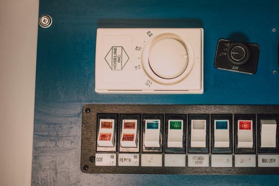
Powering Off Your Heating System

Before commencing any work on your heating system’s thermostat wiring, it is absolutely crucial to completely disconnect the power supply. This is a paramount safety precaution to prevent electrical shock and potential damage to both your heating system and the tado° Smart Thermostat.

Locate the circuit breaker or fuse box that controls your heating system. Identify the correct breaker or fuse – it’s often labeled, but if not, you may need to test them individually. Switch the breaker to the ‘off’ position or remove the fuse entirely.

Double-check that the power is indeed off by attempting to turn on your heating system. If it doesn’t respond, you’ve successfully disconnected the power. It’s also advisable to inform other household members that you are working on the heating system and that it should not be used during this time. Safety first!

Removing the Old Thermostat

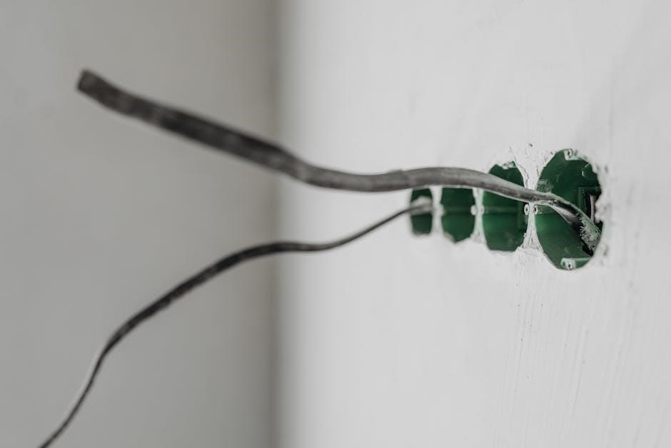
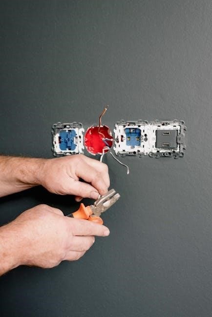
With the power safely disconnected, you can now proceed to remove your existing thermostat. Begin by carefully removing the thermostat cover – it usually snaps off or is held in place by small screws. Take a photograph of the existing wiring connections before disconnecting anything. This photo will serve as a vital reference during the tado° installation process.

Gently disconnect the wires one at a time, labeling each wire as you remove it. Use the labels provided in the tado° kit, or create your own. Avoid letting the wires fall back into the wall. Once all wires are disconnected, carefully remove the old thermostat backplate from the wall.

Be mindful of any wall anchors or screws used to secure the old backplate. You may need these to mount the tado° backplate later. Dispose of the old thermostat responsibly.

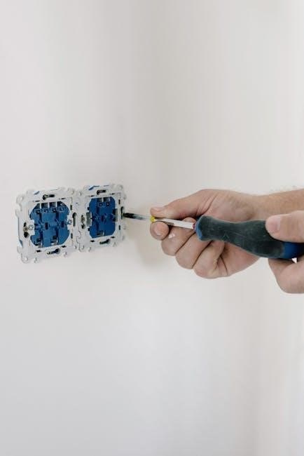
Wiring the tado° Smart Thermostat

Using the photograph and labels from the previous step, connect the wires to the tado° Smart Thermostat backplate. The tado° app provides a wiring guide tailored to your heating system, ensuring correct connections. Carefully insert each wire into the corresponding terminal on the backplate, ensuring a secure fit.

Double-check all connections against your wiring diagram and the tado° app’s instructions. Incorrect wiring can damage your heating system or the tado° device. If you are unsure about any connection, consult a qualified heating engineer.

Ensure no bare wires are exposed to prevent short circuits. Once all wires are securely connected, gently tuck them back into the wall cavity, being careful not to strain the connections.

Mounting the tado° Smart Thermostat

Securely attach the backplate to the wall using the provided screws, ensuring it is level. Then, connect the thermostat to the backplate and secure it firmly.

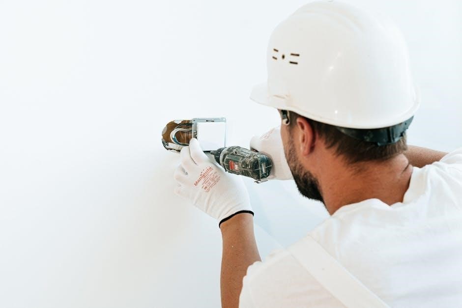
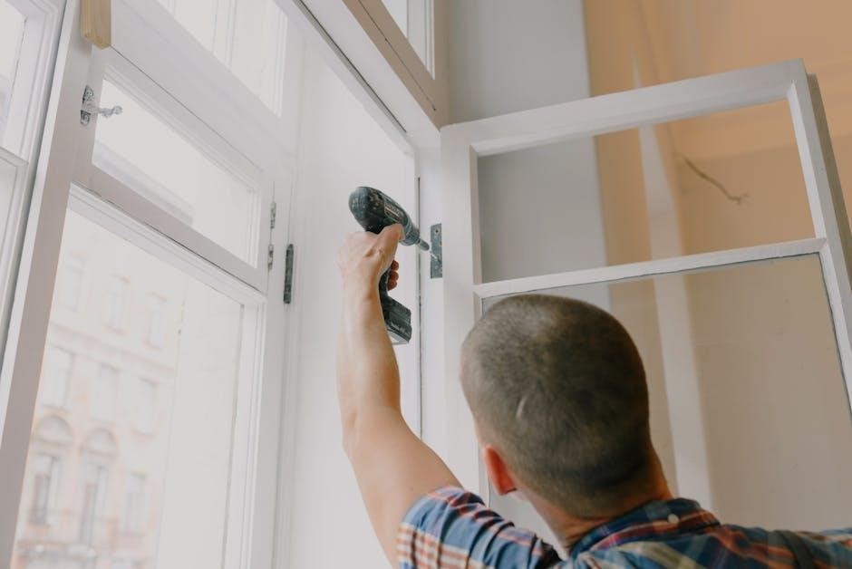
Attaching the Backplate

Before mounting, ensure the heating system is completely powered off at the breaker for safety. Position the tado° backplate on the wall where your old thermostat was located, using it as a template to mark the screw holes. Utilize a drill to create pilot holes at the marked locations – appropriate drill bit size will depend on your wall material.

Insert the provided wall plugs into the drilled holes, if necessary, for a secure fit. Align the backplate with the holes and fasten it to the wall using the screws included in the kit. Ensure the backplate is level to guarantee proper thermostat alignment and functionality. Tighten the screws firmly, but avoid over-tightening, which could damage the wall or the backplate itself. A properly secured backplate is crucial for a stable and reliable tado° installation.

Connecting the Thermostat to the Backplate

With the backplate securely mounted, carefully align the tado° Smart Thermostat with it. Gently push the thermostat onto the backplate; you should hear a distinct click indicating a secure connection. Ensure the thermostat sits flush against the wall and doesn’t wobble, signifying a proper fit. Do not force the connection – if it doesn’t click easily, double-check the alignment.

Once connected, verify that the thermostat’s display illuminates, confirming it’s receiving power from the wiring. A stable connection between the thermostat and backplate is vital for consistent operation. If the display remains dark, revisit the wiring steps to ensure correct connections. A secure and illuminated connection confirms readiness for app configuration and smart heating control.

Securing the Device

After connecting the thermostat to the backplate, ensure it’s firmly secured to prevent accidental detachment. While the click mechanism provides initial security, consider the environment and potential for disturbance. Gently tug on the thermostat to confirm it’s robustly attached to the backplate; it shouldn’t come loose.

For added security, especially in high-traffic areas, you can utilize the provided screws (if applicable) to further fasten the thermostat to the wall. Be cautious not to overtighten the screws, as this could damage the device or the wall. A securely mounted thermostat ensures reliable operation and prevents potential wiring issues. Regular checks can confirm continued secure attachment over time.

Configuring the tado° App

Utilize the tado° app to personalize your heating experience, adding the thermostat, setting schedules, and configuring hot water control for optimal comfort and savings.

Adding the Thermostat to Your tado° Account

Begin by ensuring your Internet Bridge is successfully connected to your home’s Wi-Fi network and that the tado° app is installed on your smartphone or tablet. Open the app and, if prompted, create a new account or log in to your existing one.

Within the app, navigate to the “Add Device” section, typically found under settings or a similar menu option. The app will guide you through the process of discovering your new tado° Smart Thermostat.

You’ll likely be asked to press a button on the thermostat itself to initiate pairing. The app will then search for and connect to the thermostat, displaying its status throughout the process.

Once connected, you’ll be prompted to name the thermostat and assign it to a specific room within your home. This allows for zone-based heating control. Ensure the thermostat is correctly identified and placed in the appropriate location within the app for accurate scheduling and automation.

Setting Up Heating Schedules

Within the tado° app, navigate to the scheduling section for the thermostat you’ve added. Here, you can create personalized heating schedules tailored to your lifestyle and preferences. The app offers pre-set schedules, like “Home,” “Away,” and “Sleep,” which you can customize.

You can define different temperatures for various times of the day and days of the week. For example, lower the temperature while you’re at work and increase it before you return home. The app’s intuitive interface allows for easy adjustments and modifications.

Leverage geofencing features to automatically adjust the heating based on your location. Tado° can detect when you leave or approach home, optimizing energy usage. Explore advanced settings for vacation mode and manual overrides for ultimate control. Regularly review and refine your schedules to maximize comfort and savings.

Hot Water Control Configuration (if applicable)

If your tado° system includes hot water control, access the dedicated section within the app. This feature allows you to manage your hot water tank’s heating schedule independently from your central heating. You can set specific times for the water to heat up, ensuring hot water is available when needed while minimizing energy waste.

Configure schedules to align with your daily routines, such as heating water before morning showers and evenings. Explore options for boosting the hot water temperature temporarily for specific needs. The app provides insights into your hot water usage, helping you identify potential savings.

Ensure compatibility with your hot water system before enabling this feature. Adjust settings carefully to avoid scalding or insufficient hot water. Regularly monitor performance and refine schedules for optimal efficiency and comfort.

Troubleshooting Common Installation Issues

Addressing connectivity, power, and pairing problems is crucial for a smooth setup; the tado° app offers guided solutions for these frequent installation challenges.

Bridge Connectivity Problems

If the tado° Internet Bridge fails to connect, first ensure your router is broadcasting on the 2.4 GHz band, as the Bridge doesn’t support 5 GHz. Verify the Bridge is within a reasonable range of your router – excessive distance or obstructions can weaken the signal.

Restart both your router and the tado° Bridge; unplug them for 30 seconds, then plug the router back in first, waiting for it to fully initialize before plugging in the Bridge. Double-check your Wi-Fi password entered within the tado° app during setup.

Confirm that your router isn’t blocking the Bridge’s access; consult your router’s manual for instructions on checking firewall settings or MAC address filtering. If problems persist, try moving the Bridge to a more central location in your home, away from potential interference sources like microwaves or cordless phones. Finally, ensure the Bridge has a dedicated IP address.

Thermostat Not Powering On

If the tado° Smart Thermostat doesn’t power on after installation, meticulously re-examine the wiring connections. Ensure the wires are securely inserted into the correct terminals on both the thermostat backplate and your heating system’s terminal block. Double-check that the heating system’s power is completely switched off at the breaker before and during wiring.

Verify sufficient voltage is reaching the thermostat; a multimeter can be used to test this, but only if you are comfortable and competent with electrical testing. Confirm compatibility with your heating system – some systems may require a common (C) wire, and if absent, a tado° Power+ adapter might be necessary.

Inspect the thermostat’s batteries (if applicable) and replace them with fresh ones. If still no power, consult a qualified electrician to rule out any issues with your heating system’s power supply or wiring.

App Pairing Failures

Experiencing difficulties pairing your tado° Smart Thermostat with the app? First, ensure your smartphone or tablet is connected to a stable 2.4 GHz Wi-Fi network – tado° currently doesn’t support 5 GHz networks. Confirm Bluetooth is enabled on your mobile device, as it’s crucial for the initial pairing process.

Restart both the tado° Internet Bridge and your Smart Thermostat. Within the tado° app, try the “Add Device” process again, carefully following the on-screen instructions. Ensure the thermostat is in pairing mode (usually indicated by a flashing light).

If problems persist, temporarily disable any VPN or firewall settings on your network. Check the tado° support website for known issues or firmware updates. If all else fails, contact tado° customer support for personalized assistance.

honeywell thermostat lyric manual

Honeywell’s Lyric thermostat blends convenience and energy efficiency‚ learning your home’s patterns—not relying on rigid schedules. This guide simplifies understanding
your new thermostat‚ ensuring safe and effective operation.

The Lyric offers automated control‚ utilizing geofencing and smart algorithms for optimal comfort and savings‚ as detailed in the user manual (RCH9310WF5003/W).

What is the Honeywell Lyric Thermostat?

The Honeywell Lyric thermostat represents a leap forward in home climate control‚ moving beyond traditional programmable models. It’s a Wi-Fi enabled smart thermostat designed for effortless operation and substantial energy savings. The Lyric learns your heating and cooling preferences‚ adapting to your lifestyle rather than requiring complex scheduling.

Available in both round (RCH9310WF5003/W) and T6/T6R PRO versions‚ it offers remote access via the Lyric app‚ allowing adjustments from anywhere. Its core function is to maintain desired temperatures efficiently‚ utilizing features like geofencing and advanced algorithms. Installation requires a competent person‚ and careful reading of the user guide is crucial.

Key Features and Benefits

The Honeywell Lyric boasts several key advantages. Wi-Fi connectivity enables remote control via smartphone‚ offering convenience and energy management. Geofencing automatically adjusts temperatures based on your location‚ maximizing savings when you’re away. The thermostat learns your routines‚ creating a personalized comfort profile.

Further benefits include a user-friendly interface‚ detailed reporting on energy usage‚ and compatibility with various heating and cooling systems. Advanced features like binding/unbinding devices enhance system integration. The fixed 0°F deadband ensures consistent temperature control‚ as outlined in the manual (RCH9310WF5003/W).

Installation and Setup

Proper installation‚ utilizing the included UWP mounting system‚ is crucial. Carefully verify all package contents before beginning‚ and ensure a competent person handles installation for safety.

Package Contents Verification

Before beginning installation‚ meticulously verify all components are present within the package. You should find the Lyric T6 PRO Wi-Fi Thermostat itself‚ alongside the UWP Mounting System‚ essential for secure attachment to your wall.

Confirm the inclusion of any necessary mounting hardware – screws and wall anchors – to ensure a stable installation. Review the user guide (RCH9310WF5003/W) for a detailed parts list and visual representation. Missing components can delay setup‚ so address any discrepancies immediately. Proper verification streamlines the installation process and prevents frustration.

Mounting the Thermostat (UWP System)

Utilizing the UWP Mounting System‚ begin by removing your existing thermostat’s baseplate. Carefully label all wires before disconnecting them – a photograph is highly recommended! Attach the UWP baseplate to the wall‚ ensuring it’s level.

Secure it with the provided screws. Connect the labeled wires to the corresponding terminals on the UWP baseplate. Finally‚ snap the Lyric thermostat onto the mounted baseplate. Refer to the user guide (RCH9310WF5003/W) for detailed wiring diagrams and illustrations to ensure correct installation.

Connecting to Wi-Fi

To connect your Lyric thermostat to Wi-Fi‚ ensure your home network is active and you have the password readily available. On the thermostat display‚ navigate to the settings menu and select “Connect to Wi-Fi.” The thermostat will scan for available networks.

Choose your network from the list and enter the password when prompted. Once connected‚ the thermostat will display a confirmation message. This enables remote control and access to advanced features via the Lyric app. See the user guide (RCH9310WF5003/W) for troubleshooting connectivity issues.

Understanding the Thermostat Interface

The Lyric thermostat features an intuitive display with clear icons. Navigating the menu is straightforward‚ offering access to settings and scheduling options for personalized comfort.

Display Overview and Icons

The Honeywell Lyric thermostat’s display presents crucial information at a glance. You’ll find the current temperature prominently displayed‚ alongside the setpoint temperature. Icons indicate the current system mode – heating‚ cooling‚ or auto.

A Wi-Fi symbol confirms a successful connection‚ enabling remote control via the Honeywell Home app. Other icons represent fan operation‚ system status‚ and alerts. A five-second press accesses the advanced menu for deeper customization.

Understanding these icons is key to efficiently managing your home’s climate‚ as detailed in the user guide (RCH9310WF5003/W). The interface is designed for user-friendliness‚ providing a clear and concise overview of your system’s operation.

Navigating the Menu System

The Honeywell Lyric thermostat features an intuitive menu system accessed via the touchscreen display. Swiping or tapping allows you to cycle through options like schedule‚ settings‚ and device information. The user guide (RCH9310WF5003/W) provides a detailed walkthrough of each menu item.

To access advanced settings‚ a sustained five-second press is required. Within the menus‚ you can adjust temperature preferences‚ configure geofencing‚ and manage connected devices. Clear navigation is essential for customizing your comfort settings.

Remember to save any changes made to ensure they are implemented correctly.

Advanced Menu Access (5-Second Press)

Accessing the advanced menu on your Honeywell Lyric thermostat requires a deliberate action: a five-second press on the thermostat’s screen. This unlocks settings beyond typical temperature adjustments‚ enabling features like device binding and clearing existing connections.

The user guide (32317085-007 A) explicitly instructs users to utilize this method for troubleshooting connectivity issues or re-establishing device communication. Within this menu‚ proceed with caution‚ as incorrect adjustments can impact functionality.

Remember‚ a competent person should handle complex settings!

Programming and Scheduling

Lyric thermostats allow customized heating/cooling schedules‚ adapting to your lifestyle. Geofencing automates temperature adjustments based on your location‚ maximizing comfort and savings.

Setting the Date and Time

Accurate date and time settings are crucial for proper scheduling and geofencing functionality within the Honeywell Lyric thermostat. The initial setup process will guide you through this configuration‚ typically accessed via the thermostat’s menu system.

Navigate to the settings menu‚ often represented by a gear icon‚ and select the “Date/Time” option. From there‚ you can manually adjust the month‚ day‚ year‚ hour‚ and minute.

Ensure synchronization with your Wi-Fi network for automatic updates‚ preventing manual adjustments. Correct time settings are fundamental for reliable automated control and energy savings.

Creating a Heating/Cooling Schedule

The Honeywell Lyric thermostat allows for customized heating and cooling schedules to optimize comfort and energy usage. Access the scheduling feature through the main menu‚ selecting options like “Schedule” or “Programming.”

You can define different temperature setpoints for various times of the day and days of the week. Create distinct periods – such as “Wake‚” “Leave‚” “Return‚” and “Sleep” – each with its preferred temperature.

The Lyric’s intuitive interface simplifies schedule creation‚ ensuring a comfortable and efficient home environment tailored to your lifestyle.

Using Geofencing for Automated Control

The Honeywell Lyric thermostat’s geofencing feature provides automated temperature adjustments based on your location. By enabling this function within the Lyric app‚ the thermostat detects when you leave or approach your home.

When you exit a defined geofence radius‚ the thermostat automatically switches to an energy-saving “Away” mode. Upon re-entry‚ it returns to your preferred “Home” temperature‚ ensuring comfort without manual adjustments.

This intelligent automation maximizes energy savings and provides a consistently comfortable indoor climate‚ adapting to your daily routines seamlessly.

Advanced Features and Settings

The Lyric thermostat offers customizable settings like differential adjustments and device binding. Understanding these features—detailed in the manual—unlocks personalized control and optimal system performance.

Understanding Differential Settings

Differential settings dictate the minimum temperature difference between heating and cooling activation. The Honeywell Lyric thermostat utilizes this to prevent rapid cycling‚ enhancing system efficiency and longevity. It’s crucial to note‚ however‚ that the Lyric thermostat’s differential is not the same as deadband.

The manual clarifies that differential represents the allowable temperature swing for switching between heating and cooling modes. Adjusting this setting impacts how quickly the system responds to temperature changes. A smaller differential means more frequent‚ but potentially gentler‚ adjustments‚ while a larger differential allows for greater swings before activation.

Properly configuring the differential‚ as outlined in the user guide (RCH9310WF5003/W)‚ contributes to a more comfortable and energy-efficient home environment.

Deadband Temperature Explained (Fixed at 0°F)

Deadband refers to the temperature range around the setpoint where neither heating nor cooling activates‚ preventing constant cycling. Unlike differential‚ the Honeywell Lyric thermostat employs a fixed deadband of 0°F. This means the system is designed to react very closely to temperature fluctuations around your desired setting.

The thermostat’s algorithm manages this fixed deadband‚ optimizing for consistent comfort without the short-cycling issues that can occur with adjustable deadband settings. The user manual (RCH9310WF5003/W) explicitly states this non-adjustable feature‚ emphasizing Honeywell’s approach to precise temperature control.

This fixed setting simplifies operation and ensures efficient performance.

Binding and Unbinding Devices

Binding refers to connecting your Lyric thermostat to other compatible Honeywell Home devices‚ enabling coordinated control. If experiencing connectivity issues‚ the user guide (32317085-007 A) advises accessing the advanced menu – achieved by a 5-second press on the thermostat face.

Within this menu‚ locate the ‘Binding’ option. To re-establish a connection‚ first ‘clear’ any existing binding‚ then initiate the binding process again. This effectively resets the communication link between devices.

Ensure a competent person performs installation‚ as incorrect binding can disrupt system functionality.

Troubleshooting Common Issues

Connectivity problems‚ unresponsive thermostats‚ or inaccurate temperature readings are addressed in the Lyric manual. Re-binding devices or checking Wi-Fi can resolve many issues.

Connectivity Problems

If your Honeywell Lyric thermostat experiences connectivity issues‚ the user guide (RCH9310WF5003/W) suggests several troubleshooting steps. First‚ ensure your home Wi-Fi network is functioning correctly. Then‚ within the thermostat’s advanced menu (accessed by a 5-second press)‚ attempt to reconnect to your Wi-Fi network.

Clearing the current device binding and re-binding it can also resolve connection problems. Verify the thermostat is within range of your Wi-Fi router. If issues persist‚ consult Honeywell’s support website (lyric.honeywell.com) for further assistance and detailed instructions.

Thermostat Not Responding

Should your Honeywell Lyric thermostat become unresponsive‚ begin by checking the power supply. Ensure the thermostat is securely mounted using the UWP system and receiving adequate power. A brief power cycle – turning the system off and on at the breaker – can sometimes resolve the issue.

The user guide (RCH9310WF5003/W) advises accessing the advanced menu (5-second press) to check device binding. If unresponsive after these steps‚ a qualified installer may be required‚ as proper installation is crucial for reliable operation.

Incorrect Temperature Readings

If your Honeywell Lyric thermostat displays inaccurate temperatures‚ first verify its location isn’t affected by drafts‚ sunlight‚ or heat-generating appliances. The thermostat’s internal sensor needs a stable environment for precise readings. While the deadband temperature is fixed at 0°F‚ differential settings—the minimum temperature difference between heating and cooling—can influence perceived accuracy.

Consult the user guide (RCH9310WF5003/W) for details on understanding these settings. If the problem persists‚ recalibrating the thermostat or contacting Honeywell support may be necessary for a reliable solution.

Safety Information and Warnings

Installation must be performed by a qualified professional to avoid product damage or hazardous conditions. Carefully read all instructions before proceeding‚ as detailed in the manual.

Important Safety Precautions

Prior to installation or servicing‚ always disconnect power to the heating and cooling system at the breaker panel to prevent electrical shock. Failure to do so could result in serious injury or death. This device is intended for indoor use only and should not be exposed to direct sunlight or moisture.

Ensure the thermostat is mounted securely using the provided UWP system‚ avoiding locations near drafts or heat sources that could affect temperature readings. Do not attempt to disassemble or repair the thermostat yourself; contact a qualified technician for assistance. Always follow local electrical codes during installation.

Read these instructions carefully and retain them for future reference. Ignoring these precautions can damage the product and create a potentially hazardous situation. Manufactured for Honeywell by ACS-ECC EMEA.

Qualified Installer Requirement

Installation of the Honeywell Lyric thermostat should be performed by a competent and qualified technician familiar with HVAC systems and low-voltage wiring. Improper installation can lead to system malfunction‚ inaccurate temperature control‚ and potential safety hazards.

A qualified installer will ensure correct wiring connections‚ proper system configuration‚ and adherence to all applicable local codes and regulations. They possess the necessary expertise to diagnose and resolve any compatibility issues with your existing heating and cooling equipment.

Attempting self-installation without adequate knowledge is strongly discouraged. Refer to the user guide (RCH9310WF5003/W) for detailed wiring diagrams and specifications‚ but always prioritize professional installation for optimal performance and safety.

Resources and Support

For comprehensive assistance‚ visit lyric.honeywell.com. Download the complete user guide (RCH9310WF5003/W) from thermostat.guide for detailed instructions and troubleshooting tips.

Honeywell Lyric Website (lyric.honeywell.com)

The official Honeywell Lyric website‚ lyric.honeywell.com‚ serves as a central hub for all your thermostat needs. Here‚ you’ll discover a wealth of resources‚ including frequently asked questions addressing common issues and detailed support articles.

Users can access downloadable manuals‚ such as the RCH9310WF5003/W guide‚ offering in-depth explanations of features and setup procedures. The site also provides access to the latest software updates‚ ensuring your thermostat operates with optimal performance and security.

Furthermore‚ Honeywell’s online support portal allows direct contact with their customer service team for personalized assistance‚ troubleshooting‚ and warranty information; Explore interactive tutorials and videos to maximize your Lyric thermostat’s potential.

User Guide Download (RCH9310WF5003/W)

The comprehensive user guide‚ identified as RCH9310WF5003/W‚ is readily available for download from various online sources‚ including thermostat.guide and the official Honeywell Lyric website (lyric.honeywell.com). This document is crucial for understanding all aspects of your thermostat’s functionality.

Within its pages‚ you’ll find detailed instructions on installation‚ setup‚ programming schedules‚ and navigating the advanced menu system – accessed by a 5-second press. It clarifies concepts like differential settings and explains the fixed 0°F deadband.

The guide also provides essential safety precautions and troubleshooting steps for common issues like connectivity problems or unresponsive displays‚ ensuring a smooth user experience.

lg gas double oven manual

LG Gas Double Oven Manual: A Comprehensive Guide

This manual provides detailed instructions for LG gas double oven operation, safety, features, troubleshooting, and maintenance—ensuring optimal performance and longevity․

Understanding Your LG Double Oven

Your LG gas double oven is engineered for versatile cooking, featuring two independent oven cavities for simultaneous meal preparation․ This eliminates the need for multiple appliances, saving valuable kitchen space and time․ The upper oven is typically smaller, ideal for broiling, baking smaller dishes, or warming food, while the larger lower oven excels at roasting large items or handling multiple baking sheets․

Familiarize yourself with the oven’s components: the control panel, oven racks, burners, and interior lighting․ Understanding these elements will enhance your cooking experience․ Dual-oven gas ranges are exceptional for preparing greater quantities of food, offering flexibility and efficiency․ Remember to always refer to the complete manual for detailed specifications and safety guidelines specific to your model․

Safety Precautions

Prioritize safety by ensuring proper gas connections, ventilation, and carbon monoxide detection․ Always follow all warnings and instructions in this manual․

Gas Supply and Connections

Ensuring a safe and reliable gas supply is paramount for your LG double oven’s operation․ This oven is designed for use with natural gas or propane (LP), but conversion may be required․ A qualified technician must perform all gas connections and leak tests․

Verify your gas supply matches the oven’s requirements, detailed on the model’s rating plate․ Never attempt to modify gas lines yourself․ Inspect the connection for any damage before use․ Proper shut-off valves should be readily accessible․

Always use a gas leak detector solution to confirm tight connections after installation or servicing․ If you smell gas, immediately shut off the supply, evacuate the area, and contact your gas company or a qualified service technician․

Carbon Monoxide Detection

Your LG gas double oven produces carbon monoxide (CO) during normal operation․ While designed with safety features, proper ventilation and CO detection are crucial․ Install a CO alarm near the oven, following the manufacturer’s instructions for placement and maintenance․

Ensure the oven’s venting system is unobstructed and functioning correctly․ Never block or cover the oven’s air intake or exhaust vents․ Regular inspection of the burner flames is vital; a yellow or flickering flame indicates incomplete combustion and potential CO buildup․

If the CO alarm sounds, immediately ventilate the area, evacuate, and contact emergency services․ Do not re-enter until the source of CO is identified and resolved by a qualified technician․

Oven Features and Functions

Explore advanced cooking capabilities, including convection, self-cleaning options, and precise temperature control, designed to enhance your culinary experience with this LG oven․

Convection Cooking Explained

Convection cooking utilizes a fan to circulate hot air throughout the oven cavity, resulting in faster and more even cooking compared to traditional baking methods․ This technology ensures consistent temperatures, eliminating hot spots and reducing cooking times by approximately 25-30%․

LG gas double ovens often feature true convection, meaning a heating element is positioned near the fan, actively reheating the air as it circulates․ This maintains consistent heat even with frequent door openings․ For optimal results, reduce the recipe temperature by 25°F when using convection․

Convection is ideal for roasting meats, baking cookies, and preparing multiple dishes simultaneously․ Experiment with the convection settings to discover how they can elevate your favorite recipes and streamline meal preparation․

Self-Cleaning Cycle Operation

LG gas double ovens offer a self-cleaning cycle utilizing high temperatures to burn off food residue, eliminating the need for manual scrubbing․ Before initiating the cycle, remove all racks, cookware, and any loose debris from both oven cavities․

Select the self-clean option on the control panel and choose the desired cycle length (typically 2-4 hours)․ The oven door will automatically lock for safety during operation and remain locked until cooled․ Ensure adequate ventilation during the cycle, as it may produce odors․

Once complete, allow the oven to cool completely before wiping away any remaining ash․ Always refer to the full manual for specific instructions and safety precautions related to your model’s self-cleaning function․

Temperature Calibration

Maintaining accurate oven temperature is crucial for consistent cooking results․ LG gas double ovens allow for temperature calibration to adjust the displayed temperature if it deviates from the actual oven temperature․

To calibrate, access the oven settings through the control panel․ You’ll typically find a “Temperature Calibration” or “Oven Offset” option․ Use a separate oven thermometer to verify the oven’s accuracy at a specific temperature (e․g․, 350°F)․

Adjust the calibration setting in increments (usually 5°F or 10°F) until the oven thermometer matches the displayed temperature․ Always consult your specific model’s manual for detailed calibration instructions and safety guidelines․

Using the Control Panel

The LG gas double oven’s control panel features a digital display and intuitive buttons for selecting modes, setting temperatures, and managing oven functions․

Digital Display and Buttons

The LG gas double oven’s digital display provides clear readouts of the current oven temperature, cooking time remaining, and selected oven mode; Buttons are logically arranged for easy operation․

The ‘Oven Select’ button allows you to switch between the upper and lower oven compartments․ Dedicated buttons control baking, broiling, roasting, and convection functions․

A ‘Timer’ button sets cooking durations, while ‘Delay Start’ schedules cooking to begin at a later time․ Numeric buttons input temperature and time values․ The ‘Clear/Off’ button cancels selections or turns off the oven․

The display also illuminates error codes if issues arise, prompting troubleshooting․ Familiarizing yourself with these controls ensures efficient and precise oven usage․

Setting the Clock

Accurate timekeeping is crucial for utilizing the oven’s timer and delay start functions․ To set the clock on your LG gas double oven, first press the ‘Clock’ button․ The hour display will begin to flash․

Use the numeric keypad to enter the correct hour, then press the ‘Clock’ button again to confirm․ The minute display will now flash; enter the correct minutes using the keypad and press ‘Clock’ to finalize․

Ensure you select the correct AM or PM designation if your model requires it․

A properly set clock ensures the timer and delay start features operate as intended, providing convenient and precise cooking control․

Oven Mode Selection

Your LG gas double oven offers a variety of cooking modes to suit different recipes․ To select a mode, press the ‘Mode’ button repeatedly until the desired function appears on the digital display․

Available modes typically include Bake, Broil, Roast, Convection Bake, and Warm․ Each mode optimizes temperature and heating elements for specific cooking tasks․

The upper and lower ovens can be controlled independently, allowing for simultaneous cooking at different temperatures and modes․

Refer to the ‘Cooking Modes Detailed’ section for specific instructions on utilizing each function for optimal results․

Cooking Modes Detailed

Explore detailed instructions for Bake, Broil, and Roast modes, maximizing your LG gas double oven’s potential for perfectly cooked meals every time․

Bake Mode Instructions

Bake mode utilizes direct heat from the bottom burner, ideal for cakes, cookies, casseroles, and breads․ To initiate, select “Bake” on the control panel and set your desired temperature․ Preheating is crucial; allow the oven to reach the set temperature before placing food inside for consistent results․

For optimal baking, position racks in the center of the oven․ Adjust baking time based on the recipe, checking for doneness using a thermometer or visual cues․ Remember that convection bake, if available, offers more even heating․ Avoid opening the oven door frequently during baking to maintain a stable temperature․ Always use oven-safe cookware and follow recipe guidelines for best outcomes․

Broil Mode Guidelines

Broil mode employs intense, direct heat from the top burner, perfect for browning, searing, and finishing dishes․ Select “Broil” on the control panel and preheat the oven for several minutes․ Position the oven rack closest to the broiler element for maximum heat intensity, or adjust for gentler broiling․

Always use broil-safe cookware, such as metal or oven-safe glass․ Monitor food closely during broiling, as it cooks rapidly and can burn easily․ Leaving the oven door slightly ajar can help regulate temperature and prevent excessive smoking․ Never use aluminum foil on the oven bottom during broiling․ For best results, pat food dry before broiling to promote browning․

Roast Mode Techniques

Roast mode utilizes consistent, moderate heat, ideal for cooking larger cuts of meat, poultry, and vegetables․ Select “Roast” on the control panel and set the desired temperature, typically between 325°F and 375°F․ Place the food on a roasting rack inside a pan to allow for even heat circulation․

For optimal results, baste the food periodically with its own juices or a marinade to maintain moisture and enhance flavor․ Consider using a meat thermometer to ensure the internal temperature reaches a safe level․ Roasting often benefits from lower temperatures and longer cooking times, yielding tender and flavorful results․

Troubleshooting Common Issues

This section details solutions for frequent problems like heating failures, error codes, and igniter malfunctions, helping you resolve issues quickly and safely․

Oven Not Heating

If your LG gas double oven isn’t heating, first verify the gas supply is connected and the valve is open․ Check the igniter; a visible glow indicates it’s attempting to light, but a lack of glow suggests a faulty igniter needing replacement․ Ensure the oven’s control panel is correctly set to a bake or roast mode, and the temperature is appropriately programmed․

A common issue is a blocked burner port, preventing gas flow․ Carefully clean the burner using a wire brush or pin to remove any obstructions․ If the issue persists, examine the oven’s safety valve – a malfunctioning valve will prevent gas from reaching the burner․ Always disconnect the gas supply before attempting any burner or valve inspection․ If you’re uncomfortable with these checks, contact a qualified technician․

Error Codes and Meanings

LG gas double ovens utilize error codes to diagnose internal issues․ A code like “E1” often indicates a gas supply problem, requiring verification of the gas valve and connection․ “E2” frequently signals an igniter malfunction, potentially needing replacement by a qualified technician․ “E3” can point to a flame sensor issue, preventing gas flow detection and shutting down the oven for safety․

“E4” may indicate a temperature sensor failure, leading to inaccurate temperature readings․ Refer to your specific model’s manual for a complete list of error codes and their corresponding solutions․ Attempting repairs without proper knowledge can be dangerous; always prioritize safety and consult a professional if unsure․ Document the error code before contacting LG support for efficient assistance․

Igniter Problems

A faulty igniter is a common cause of gas oven failure․ If the oven clicks repeatedly but doesn’t ignite, the igniter may be weak or broken․ Visually inspect the igniter for cracks or damage; a glowing igniter indicates functionality, while a dark one suggests a problem․ Ensure the igniter receives adequate voltage – a multimeter can verify this․

Cleaning around the igniter is crucial, as debris can hinder ignition․ Replacing the igniter is often necessary, but requires disconnecting the gas supply and electrical connections – proceed with extreme caution or hire a qualified technician․ Incorrect installation can lead to gas leaks and safety hazards․ Always test the oven after replacement․

Cleaning and Maintenance

Regular cleaning preserves your LG gas double oven’s performance and lifespan․ This section details interior, exterior, and burner maintenance procedures for optimal results․

Interior Cleaning Procedures

Routine interior cleaning maintains oven efficiency and food quality․ Before starting, ensure the oven is cool and disconnected from power․ Remove racks, broiler pan, and any accumulated debris․ For light cleaning, a damp cloth with mild dish soap is sufficient; avoid abrasive cleaners which can damage the enamel․

For baked-on spills, create a paste of baking soda and water, apply to the affected areas, and let sit for 20-30 minutes before gently scrubbing․ Rinse thoroughly with a clean, damp cloth․ The self-cleaning cycle, when appropriate, offers a convenient alternative, but always follow the safety guidelines outlined in the manual․ Remember to wipe up any remaining residue after the cycle completes, ensuring a spotless interior․

Exterior Cleaning Recommendations

Maintaining a clean exterior enhances your LG gas double oven’s appearance and prevents buildup․ Always disconnect power before cleaning․ Use a soft cloth dampened with warm, soapy water to wipe down the control panel, door, and sides․ Avoid abrasive cleaners, scouring pads, or harsh chemicals, as these can scratch or discolor the surfaces․

For stainless steel exteriors, use a stainless steel cleaner specifically designed for appliances, following the product’s instructions carefully․ Pay attention to the door seals, ensuring they are clean and free of debris for a proper seal․ Dry all surfaces thoroughly with a clean, soft cloth to prevent water spots and streaks․ Regular cleaning prevents grime accumulation․

Burner Maintenance

Proper burner maintenance ensures efficient and safe operation of your LG gas double oven․ Regularly inspect the burner ports for any obstructions, such as food debris or spills․ Use a thin wire or needle to carefully clear any blocked ports – always disconnect the gas supply first!

Check the burner caps for proper seating and alignment․ Clean them with warm, soapy water and a non-abrasive brush․ Ensure they are completely dry before replacing them․ A qualified technician should inspect the gas supply connections annually to verify for leaks and proper function․ Never attempt to disassemble or repair the gas valve yourself; this is a safety hazard․

Warranty Information

LG provides a comprehensive warranty covering parts and labor for your gas double oven, offering peace of mind and reliable support․

Coverage Details

The LG gas double oven warranty typically covers defects in materials and workmanship for a specified period, usually one year from the purchase date for parts and labor․ Extended warranties may be available for purchase, offering additional coverage for several years․ This standard warranty encompasses issues arising from normal residential use, including malfunctions of oven components like burners, igniters, and the control panel․

However, the warranty does not cover damage resulting from improper installation, misuse, accidents, or unauthorized repairs․ Cosmetic damages, such as scratches or dents, are also generally excluded․ It’s crucial to retain proof of purchase for warranty claims․ Registering your appliance with LG promptly after purchase streamlines the claim process, ensuring efficient service and support․

Contacting LG Support

For assistance with your LG gas double oven, several support channels are readily available․ LG’s customer service can be reached via phone at 1-800-243-0000, offering direct access to trained technicians․ Their website, lg․com/us/support, provides a comprehensive self-service portal with FAQs, troubleshooting guides, and downloadable manuals․

Live chat support is also accessible online for immediate assistance․ Furthermore, LG offers support through social media platforms like Twitter (@LGUSSupport) and Facebook․ When contacting support, have your model number and serial number readily available to expedite the process․ Detailed information regarding warranty claims and authorized service centers can also be found on the LG website․

compustar auto start manual

Compustar Auto Start Manual: A Comprehensive Guide

This manual details Compustar systems, covering installation, operation, and troubleshooting․ It assists users with remote start, lock/unlock features, and system indicators, ensuring a smooth experience․

Understanding Compustar Systems

Compustar systems represent a leading edge in vehicle security and remote start technology․ These systems are designed to enhance convenience, security, and control over your vehicle, offering a range of features tailored to modern automotive needs․ Understanding the core components and functionalities is crucial for optimal use․

At their heart, Compustar systems utilize a sophisticated radio frequency (RF) or two-way communication protocol to interact with your vehicle․ This allows for remote commands such as starting the engine, locking and unlocking doors, and activating the alarm․ The systems typically consist of a control module, a remote transmitter, and various sensors․ The control module is the brain of the system, interpreting signals from the remote and controlling vehicle functions․

Different Compustar systems cater to varying levels of complexity and features․ Basic systems offer remote start functionality, while more advanced systems include features like smartphone control, GPS tracking, and advanced security options․ Proper understanding of your specific system’s capabilities is key to maximizing its benefits․ Careful review of the system’s documentation and this manual will provide a solid foundation for operation and troubleshooting․

Types of Compustar Systems

Compustar offers a diverse portfolio of systems, categorized by features and communication methods․ The core distinctions lie between one-way, two-way, and smartphone-controlled systems, each catering to different user preferences and budgets․ Understanding these differences is vital when selecting the right system for your vehicle․

One-way systems are the most basic, transmitting signals to the vehicle but not receiving confirmation․ This means you won’t know if the command was successfully executed․ Two-way systems provide confirmation via the remote, displaying status updates like engine running or alarm triggered․ This offers increased peace of mind and control․

Smartphone-controlled systems, like Compustar’s DroneMobile, add another layer of convenience, allowing control via a mobile app․ These systems often include GPS tracking, geofencing, and vehicle health monitoring․ Furthermore, systems are often categorized by range – short, medium, and extended – impacting the distance from which commands can be issued․ Choosing the appropriate type depends on your needs, vehicle type, and desired level of control and security․

Remote Start System Features

Compustar remote start systems boast a comprehensive suite of features designed for convenience, security, and comfort․ Beyond the core remote engine start functionality, many systems offer advanced capabilities enhancing the overall user experience․ These features significantly improve vehicle ownership, especially in extreme weather conditions․

Key features include remote lock and unlock, allowing you to secure or access your vehicle from a distance․ Turbo mode provides a faster warm-up or cool-down period, while extended range systems offer greater control distance․ Many systems also incorporate automatic climate control, activating the HVAC system to pre-condition the cabin․

Advanced features, particularly in two-way and smartphone-controlled systems, include real-time vehicle status updates, alarm notifications, and GPS tracking․ Some systems even offer vehicle health monitoring, alerting you to potential maintenance needs․ Understanding these features allows you to maximize the benefits of your Compustar system and tailor it to your specific requirements, ensuring a comfortable and secure driving experience․

One-Way vs․ Two-Way Systems

Compustar offers both one-way and two-way remote start systems, each catering to different needs and budgets․ Understanding the distinctions between these types is crucial for selecting the right system for your vehicle and lifestyle․ The primary difference lies in communication capabilities and the level of feedback provided to the user․

One-way systems transmit a signal to the vehicle, initiating functions like remote start or lock/unlock․ However, they do not receive confirmation back from the vehicle․ This means you won’t know if the command was successfully executed․ Two-way systems, conversely, establish a bidirectional communication link․

This two-way communication provides real-time feedback, confirming successful operation and alerting you to any alarms triggered․ They often feature an LCD screen displaying vehicle status, such as temperature or security alerts․ While generally more expensive, two-way systems offer enhanced peace of mind and control․ Choosing between the two depends on your desired level of security, convenience, and budget considerations․

Installation & Setup

Proper installation is vital for optimal performance․ Professional installation ensures correct wiring and programming, maximizing system functionality and vehicle compatibility for a seamless experience․

Professional Installation Recommended

While some Compustar systems are designed with DIY installation in mind, professional installation is strongly recommended for most users․ This ensures a secure and reliable connection to your vehicle’s complex electrical system, minimizing the risk of damage or malfunction․ A certified installer possesses the necessary expertise, tools, and knowledge of vehicle-specific wiring diagrams to perform the installation correctly․

Incorrect wiring can lead to a variety of issues, including blown fuses, damaged modules, and even potential safety hazards․ Professionals are trained to identify and avoid these pitfalls, guaranteeing a safe and functional installation․ They also understand the intricacies of bypass module integration, which is often required to prevent security system conflicts․

Furthermore, a professional installation often includes thorough testing and programming to ensure optimal performance and compatibility with your vehicle․ This can save you valuable time and frustration in the long run․ Choosing a reputable installer provides peace of mind and maximizes the benefits of your Compustar auto start system․

Wiring Diagrams & Vehicle Compatibility

Accurate wiring diagrams are crucial for a successful Compustar installation․ Compustar provides vehicle-specific wiring diagrams through its online database and authorized dealer network․ These diagrams detail the precise location and function of each wire required for connection, ensuring compatibility and preventing damage to your vehicle’s electrical system․

Vehicle compatibility varies depending on the Compustar system model and your vehicle’s year, make, and model․ Before purchasing a system, it’s essential to verify compatibility using Compustar’s online vehicle search tool or by consulting with a professional installer․ This tool confirms whether a specific system will function correctly with your vehicle’s existing features, such as factory security systems and immobilizers․

Understanding the wiring diagram involves identifying key wires like ignition, starter, brake, and accessory power․ Proper connection of these wires is vital for the system’s operation․ Always double-check connections and use appropriate wiring connectors for a secure and reliable installation․ Incorrect wiring can lead to system malfunction or vehicle damage․

Programming the Remote

Programming your Compustar remote is essential for establishing communication with the vehicle’s control module․ The programming process typically involves a sequence of key turns and button presses, outlined in your system’s specific manual․ It’s crucial to follow these steps precisely to ensure successful pairing․

Most Compustar systems offer multiple programming methods, including automatic programming and manual programming․ Automatic programming often requires a specific sequence of ignition cycles, while manual programming involves entering a unique security code․ Refer to your manual for the correct method for your system․

If you encounter difficulties during programming, ensure the vehicle’s battery is fully charged and that there are no other active remote start systems interfering․ Some systems require a bypass module to be properly installed and functioning before remote programming can occur․ If problems persist, consult a Compustar authorized dealer for assistance․ Incorrect programming can render the remote unusable․

Bypass Module Integration

A bypass module is often a necessary component for modern vehicle compatibility with Compustar remote start systems․ These modules circumvent the vehicle’s factory security system, allowing the remote start to function without disabling essential safety features like the immobilizer․ Proper integration is paramount for reliable operation․

The bypass module connects to the vehicle’s data network, communicating with the ECU to authenticate the remote start request․ Selecting the correct bypass module for your specific vehicle make and model is critical; incorrect modules can cause system malfunctions or damage․ Professional installation is highly recommended to ensure correct wiring and configuration․

During installation, the bypass module must be programmed to recognize your vehicle’s security codes․ This process typically involves using a programming tool and following the module’s instructions․ A properly installed and programmed bypass module enables seamless remote start functionality while maintaining vehicle security․ Failure to integrate a bypass module correctly will prevent the system from operating․

Operating Your Compustar System

Effectively utilize your Compustar system with this guide․ Learn remote start, lock/unlock, turbo mode, and indicator functions for optimal performance and convenience․

Basic Remote Start Operation

Initiating your vehicle’s remote start with your Compustar system is a straightforward process, designed for convenience and ease of use․ First, ensure your vehicle is parked in a safe location and that the hood is securely closed․ Press the designated remote start button – typically marked with a power symbol or a car icon – on your Compustar remote․

The system will acknowledge the command, and your vehicle should begin to start․ You may hear a click as the system engages, followed by the engine turning over․ If the vehicle doesn’t start on the first attempt, repeat the process, ensuring no other systems are interfering․

Important considerations: The parking brake must be engaged for the remote start to function․ Some systems require a momentary press of the brake pedal after the remote start sequence is initiated․ The system will automatically shut off after a pre-programmed runtime, typically 15-30 minutes, to prevent fuel waste and ensure safety․ Familiarize yourself with your specific system’s runtime settings․ Always remain aware of your surroundings when using remote start, and never start a vehicle in an enclosed space․

Confirm operation: Verify the vehicle is running by observing the headlights or listening for the engine․ The system’s LED indicator will also confirm successful operation․

Remote Lock/Unlock Functions

Your Compustar system provides convenient remote lock and unlock capabilities, enhancing vehicle security and access․ To lock your vehicle remotely, press the lock button on your remote transmitter – usually depicted with a closed padlock symbol․ You should hear the door locks engage, and the vehicle’s security system will arm, if equipped․ The integrated LED indicator on the vehicle will typically flash to confirm locking․

To unlock your vehicle, press the unlock button – often symbolized by an open padlock․ The doors will disengage, and the security system will disarm․ Some systems offer a ‘double-unlock’ feature, requiring a second press to unlock all doors, including the trunk․

Important notes: Ensure you have a clear line of sight to your vehicle for optimal range․ If the system doesn’t respond, try moving closer or pressing the button again․ Certain models feature ‘instant unlock,’ immediately unlocking the driver’s door upon pressing the unlock button․ Be mindful of your surroundings when unlocking remotely, and always visually confirm the area is safe before approaching your vehicle․ Familiarize yourself with any specific programming options related to lock/unlock behavior․

Turbo Mode & Extended Range

Compustar systems often incorporate “Turbo Mode” and extended range features to optimize performance in challenging conditions or over greater distances; Turbo Mode, when activated, temporarily increases the remote’s transmission power, improving responsiveness, particularly in areas with potential interference – like urban environments or near radio towers․ This ensures commands are reliably received by the vehicle․

Extended range functionality utilizes advanced antenna technology and signal processing to maximize the communication distance between the remote and the vehicle․ This is especially beneficial for users who park far from their vehicle or in areas with obstructions․ Activation methods vary; some systems automatically engage extended range when the remote is outside a standard operating radius, while others require manual activation through a specific button combination․

Important considerations: Turbo Mode may reduce remote battery life․ Extended range performance is affected by environmental factors․ Always refer to your specific model’s documentation for detailed instructions on activating and utilizing these features․ Regularly check your remote’s battery level to ensure optimal functionality;

Understanding System Indicators (LEDs)

Compustar systems utilize Light Emitting Diodes (LEDs) to communicate system status and operational modes․ These indicators, typically located within the vehicle and sometimes on the remote, provide crucial feedback to the user․ A rapidly flashing LED often confirms successful remote start activation, while a slow, intermittent flash might indicate the system is in valet mode, disabling remote functions․

Different color LEDs signify different states․ A solid green light generally means the system is armed and functioning correctly․ Red flashes often signal an alarm trigger or a system malfunction requiring attention․ Blue LEDs are frequently used to indicate Bluetooth connectivity or specific feature activation․ The owner’s manual details the specific LED patterns for each model․

Decoding LED signals is vital for troubleshooting․ If the LED doesn’t respond to remote commands, check the vehicle’s battery and the system’s fuse․ Consult the manual for specific error codes represented by unique flash sequences․ Ignoring LED indicators can lead to misdiagnosis and unnecessary service calls․

Troubleshooting Common Issues

This section addresses frequent problems like unresponsive systems, limited remote range, and start failures․ It provides guidance for diagnosing and resolving typical Compustar issues quickly․

System Not Responding

If your Compustar system fails to respond to remote commands, several factors could be at play․ First, verify the remote’s battery; a weak battery is a common culprit․ Try replacing it with a fresh one․ Next, ensure there are no obstructions between the remote and the vehicle․ Metal objects or dense materials can interfere with the signal․

Check the vehicle’s battery voltage․ A significantly low voltage can prevent the system from operating correctly․ Confirm the system’s main relay is functioning – listen for a click when attempting to start the vehicle․ If no click is heard, investigate the relay and its wiring․

Inspect the system’s fuse․ A blown fuse will immediately disable the system․ Refer to your vehicle’s owner’s manual or the Compustar installation guide for the fuse location․ Finally, consider potential interference from other electronic devices․ In rare cases, strong radio frequency signals can disrupt the system’s communication․ If problems persist, professional diagnosis is recommended․

Remote Range Problems

Experiencing reduced remote start range with your Compustar system is a common concern․ Several factors can contribute to this issue․ Firstly, environmental conditions play a role; buildings, trees, and even weather can obstruct the radio frequency (RF) signal․ Ensure a clear line of sight between the remote and your vehicle whenever possible․

The remote’s antenna is crucial․ Verify it’s fully extended and undamaged․ A bent or broken antenna significantly reduces range․ Also, check for interference from other electronic devices operating on similar frequencies․ Large metal structures can also reflect or absorb the RF signal, diminishing its reach․

If you have a two-way system, confirm the remote is properly paired with the vehicle․ A weak or lost pairing can limit the range․ Consider the remote’s battery level; a low battery can reduce transmission power․ Finally, if the problem persists, a professional assessment of the antenna and system wiring is advisable to identify any potential issues․

Vehicle Not Starting

If your vehicle fails to start with the Compustar remote start system, several potential causes need investigation․ First, ensure the vehicle’s parking brake is firmly engaged – a safety feature prevents starting if it isn’t․ Verify the system isn’t in valet mode, which disables remote start functionality․ Check that all safety interlocks are met; the hood and doors must be securely closed․

A low vehicle battery can prevent starting, especially in cold weather․ Consider a battery test or jump start․ The Compustar system requires sufficient voltage to operate․ Inspect the wiring connections related to the starter, ignition, and fuel pump; loose or corroded connections can interrupt the starting process․

If a bypass module is installed, confirm it’s functioning correctly․ A faulty module can prevent the system from recognizing the vehicle’s security system․ Finally, consult the vehicle’s owner’s manual for any specific starting requirements or limitations․ If issues persist, professional diagnosis is recommended․

Alarm System Malfunctions

Compustar systems integrate with your vehicle’s security, but malfunctions can occur․ Frequent false alarms – triggered without apparent reason – indicate a potential sensor issue (door, hood, or trunk)․ Check sensor sensitivity settings within the Compustar programming, if adjustable․ A constantly sounding alarm, even with the remote, suggests a deeper problem with the system or vehicle’s security․

If the alarm doesn’t activate when triggered, investigate the siren and its wiring․ A disconnected or faulty siren won’t provide audible warning․ Ensure the shock sensor, if equipped, is properly mounted and functioning․ Interference from other electronic devices can sometimes cause alarm issues; try relocating the antenna․

A flashing security LED, even with the ignition off, might indicate a system fault․ Refer to the system’s programming manual for LED code interpretations․ If you suspect a major malfunction, disconnect the Compustar system’s power supply temporarily and consult a professional installer for diagnosis and repair․

pumpmaster 760 manual

Crosman Pumpmaster 760 Manual: A Comprehensive Guide

Welcome! This manual provides detailed instructions for operating and maintaining your Crosman 760 Pumpmaster, ensuring safe and accurate use of your new BB gun.

The Crosman Pumpmaster 760 is a classic, multi-pump pneumatic BB gun renowned for its affordability and enjoyable shooting experience. This manual serves as your guide to understanding and maximizing the potential of this popular model. It’s a spring-piston powered, lever-action rifle, meaning each pump increases the power and velocity of the BBs fired.

Designed for recreational target practice and plinking, the 760 offers a straightforward operation suitable for beginners while still providing enough power for engaging targets at reasonable distances. Understanding its mechanics, safety features, and proper maintenance – all detailed within this guide – will ensure years of reliable performance. Congratulations on choosing the Crosman Pumpmaster 760!

Safety Precautions & Warnings

Important! Always handle the Crosman Pumpmaster 760 with extreme caution. Treat it as a real firearm, even though it fires BBs. Never point the gun at anything you do not intend to shoot. Always wear eye protection to prevent injury from rebounding BBs. Adult supervision is required for users under 18 years of age.

Before each use, inspect the gun for damage. Do not use if any parts are missing or broken. Never modify the gun in any way. Keep the muzzle pointed in a safe direction during loading, pumping, and carrying. Store the gun unloaded and in a secure location inaccessible to children. Always follow all local laws and regulations regarding BB guns.

Unboxing and Parts Identification

Upon opening the box, verify all components are present: the Crosman Pumpmaster 760 rifle, a magazine, and this owner’s manual. Carefully inspect the rifle for any shipping damage. Key parts include the barrel, pump action arm, rear sight, front sight, trigger, safety mechanism, and magazine well.

Familiarize yourself with each part’s function. The pump action arm is used for cocking and propelling the BB. The rear sight allows for windage adjustment. The magazine holds approximately 200 BBs. The safety mechanism prevents accidental discharge. Refer to the detailed parts diagram later in this manual for a visual guide. Ensure you understand the location and operation of each component before proceeding.

Operating Instructions

Mastering your Crosman Pumpmaster 760 involves correctly loading BBs, understanding the pumping mechanism, practicing aiming, and making sight adjustments for accuracy.

Loading BBs into the Magazine

Begin by firmly grasping the Crosman Pumpmaster 760 magazine. Locate the BB feed port, typically a circular opening on the magazine’s side. Carefully pour BBs into this port, avoiding overfilling – approximately 175-200 BBs is ideal.

Ensure the BBs feed smoothly; gently tap the magazine to settle them. Avoid using damaged or deformed BBs, as they can cause jams. Once loaded, firmly reseat the magazine into the rifle. A proper fit is crucial for reliable feeding during operation. Always double-check that the magazine is securely locked in place before pumping and shooting.

Remember, proper loading is the first step towards a successful shooting experience!

Pumping and Cocking Mechanism

The Crosman Pumpmaster 760 utilizes a lever-action pumping system to cock the rifle and propel the BB. To operate, firmly grasp the foregrip and move the pump handle fully rearward, then forward. This action chambers a BB and compresses the spring.

Repeat this pumping motion for each shot. A complete pump stroke is essential for achieving optimal velocity and accuracy. Ensure a smooth, consistent pumping action. Avoid jerky or incomplete strokes, as this can lead to inconsistent performance. The rifle will not fire unless the pump is fully cycled.

Caution: Never attempt to disassemble the pumping mechanism without proper knowledge and tools.

Aiming and Shooting Techniques

Proper stance and aiming are crucial for accuracy with the Crosman Pumpmaster 760. Assume a stable shooting position, either standing, kneeling, or prone. Maintain a firm grip on the rifle, ensuring a consistent cheek weld against the stock.

Align the front sight with the rear sight and your target. Focus on the target, not the sights themselves. Slowly squeeze the trigger to avoid jerking the rifle. Follow through with your aim even after the shot is fired.

Practice consistent technique to improve accuracy. Remember to pump the rifle before each shot. Varying your target distance will help refine your skills.

Adjusting the Rear Sight

The Crosman Pumpmaster 760 features an adjustable rear sight for windage correction. To adjust, locate the small screw on the rear sight base. Loosen the screw slightly using a screwdriver – do not remove it completely!

Gently drift the sight left or right to align with your target. Moving the sight left will correct for shots landing to the right, and vice versa. Tighten the screw once the desired alignment is achieved.

Make small adjustments and test your accuracy after each change. Consistent grouping is key. Repeat the process until your shots consistently hit the target.

Maintenance and Care

Regular cleaning and lubrication are vital for optimal performance and longevity of your Crosman Pumpmaster 760. Follow the guidelines provided within!

Cleaning the Barrel

Maintaining a clean barrel is crucial for accuracy and preventing BB jams in your Crosman Pumpmaster 760. Before cleaning, always ensure the rifle is unloaded and safe. Use a specialized BB gun cleaning rod with a felt or cotton tip.

Insert the rod from the breech end (rear) of the barrel to avoid damaging the muzzle. Gently push the cleaning rod through the barrel several times, using a dry cloth initially to remove loose debris.

For stubborn residue, apply a small amount of silicone oil or a dedicated BB gun barrel cleaner to the cleaning patch. Avoid using petroleum-based solvents, as they can damage the rifle’s components. After cleaning, inspect the barrel for any remaining obstructions.

Lubrication Guide

Proper lubrication ensures smooth operation and longevity of your Crosman Pumpmaster 760. Avoid over-lubrication, as excess oil attracts dirt and debris. Use a silicone-based lubricant specifically designed for airguns; petroleum-based oils can damage seals.

Apply a small drop of lubricant to the pump rod, piston, and trigger mechanism. Cycle the pump action several times to distribute the lubricant evenly. Lightly lubricate the pivot points of the trigger group.

Inspect the o-rings and seals periodically; if they appear dry or cracked, apply a thin coat of silicone grease. Never lubricate the barrel itself, as this will affect BB velocity and accuracy. Regular, minimal lubrication is key to maintaining optimal performance.

Storage Recommendations

Proper storage is crucial for maintaining your Crosman Pumpmaster 760’s condition and ensuring its safety. Always store the airgun unloaded and with the safety engaged. Keep it in a secure location, inaccessible to children and unauthorized individuals.

Avoid storing the Pumpmaster 760 in areas with extreme temperatures or high humidity. These conditions can cause corrosion and damage to internal components. A dry, climate-controlled environment is ideal. Consider using a gun case or sleeve for added protection against dust and scratches.

Periodically inspect the airgun during storage for any signs of rust or deterioration. A light coating of silicone oil can help prevent corrosion.

Troubleshooting Common Issues

Addressing problems like BB jams, pumping difficulties, or inaccurate shots is now easier! This section provides solutions for common Crosman Pumpmaster 760 malfunctions.

BB Jams and Clearing Procedures

Encountering a BB jam is a common occurrence with pump-action rifles. Always ensure the Crosman Pumpmaster 760 is unloaded before attempting to clear any obstruction. First, detach the magazine. Then, carefully pull the pump fully rearward several times to eject the jammed BB.

If the BB remains lodged, gently use a wooden dowel or cleaning rod (never metal!) to dislodge it from the barrel. Avoid excessive force, as this could damage the rifling. Inspect the magazine feed tube for any debris or bent BBs that may contribute to future jams. Regular cleaning and proper BB storage will minimize jamming incidents.

Remember to wear eye protection during the clearing process. Never point the rifle at anyone while troubleshooting.

Difficulty Pumping

Experiencing resistance while pumping your Crosman Pumpmaster 760 often indicates a lubrication issue or debris within the compression chamber. First, ensure no BBs are obstructing the barrel or magazine feed tube, as this can create back pressure. Next, apply a small amount of silicone oil (see Lubrication Guide) to the pump rod and piston seal.

Work the pump several times to distribute the lubricant. If the difficulty persists, disassemble the pump assembly (refer to Detailed Parts Diagram) and inspect for any damaged or worn parts. Check the piston seal for cracks or deformation. Avoid using petroleum-based lubricants, as they can damage the seals.

Consistent pumping should become smoother with proper maintenance.

Inaccurate Shooting – Diagnosis

Consistent inaccuracy with your Crosman Pumpmaster 760 requires systematic troubleshooting. Begin by verifying proper technique – maintain a stable stance, consistent cheek weld, and smooth trigger pull (see Aiming and Shooting Techniques). Next, inspect the barrel for any obstructions or debris that could deflect the BB’s trajectory.

Carefully examine the rear sight for looseness or misalignment; adjust as needed (see Adjusting the Rear Sight). Also, ensure you are using high-quality BBs of consistent size and weight. Inconsistent BBs will lead to erratic flight patterns. Finally, check for any damage to the barrel crown, as this can significantly impact accuracy.

Remember, practice and consistent maintenance are key!

Detailed Parts Diagram

Explore detailed schematics illustrating the Crosman Pumpmaster 760’s internal components, including the magazine, trigger, pump, and barrel assemblies for easy repair.

Magazine Assembly Breakdown

Understanding the Crosman 760 magazine is crucial for reliable operation. This section details each component: the follower, spring, and magazine housing. Carefully examine the follower’s movement, ensuring smooth BB feeding. The spring provides the necessary tension to push BBs upwards.

Disassembly requires gentle pressure; avoid excessive force. Note the spring’s orientation during removal for correct reassembly. Inspect for damage or wear, replacing parts as needed. A properly assembled magazine guarantees consistent BB delivery. Refer to the diagram for visual guidance. Always ensure the magazine is securely locked into the rifle before pumping. Improper assembly can lead to malfunctions and reduced accuracy.

Trigger Mechanism Components

The trigger mechanism of the Crosman 760 is a relatively simple, yet effective design. Key components include the trigger, sear, and hammer. The sear holds the hammer back, releasing it upon trigger pull. Understanding how these parts interact is vital for maintenance. Inspect the sear for wear, as this directly impacts accuracy and safety.

Disassembly should only be performed by experienced individuals. Incorrect reassembly can create a dangerous situation. Lubricate moving parts sparingly with silicone oil. A smooth trigger pull indicates proper function. Caution: Never attempt to modify the trigger mechanism, as this could compromise safety. Refer to the detailed parts diagram for precise component locations and relationships.

Pump and Barrel Assembly

The pump assembly is central to the Crosman 760’s operation, generating the force to propel BBs. Regular inspection of the pump rod and seals is crucial for maintaining air pressure. Ensure the pump rod moves freely within the cylinder; resistance indicates potential issues. The barrel, securely attached to the receiver, guides the BB’s trajectory.

Cleaning the barrel frequently prevents BB jams and maintains accuracy. Avoid using abrasive cleaners that could damage the rifling (if present). Check for any dents or obstructions within the barrel. Proper alignment of the pump and barrel is essential for consistent performance. Caution: Never tamper with the pump’s internal components without proper knowledge.

Advanced Usage & Modifications (If Applicable)

Explore aftermarket parts for potential upgrades, but exercise caution with velocity adjustments. Prioritize long-term maintenance with a scheduled cleaning and inspection routine.

Aftermarket Parts Availability

Numerous online retailers and airgun specialty shops offer aftermarket parts for the Crosman Pumpmaster 760. Common upgrades include enhanced springs for increased velocity – exercise extreme caution with these – and improved grips for better handling and comfort.

Replacement parts, such as magazines, seals, and barrels, are generally readily available, extending the lifespan of your airgun. However, quality can vary significantly between manufacturers, so researching reputable brands is crucial. Before purchasing any aftermarket component, verify its compatibility with your specific model year of the 760.

Always prioritize safety and responsible modification; altering the airgun beyond reasonable enhancements could compromise its functionality and potentially create hazardous conditions. Consult online forums and communities dedicated to the Crosman 760 for user reviews and recommendations.

Velocity Adjustment (Cautionary)

Adjusting the velocity of your Crosman Pumpmaster 760 is possible, primarily through spring replacement, but demands extreme caution. Increasing spring tension boosts velocity, but significantly stresses internal components, potentially leading to premature wear or breakage. Always verify local laws regarding maximum permissible velocities for airguns.

Modifying the pump arm length can also influence power, but requires advanced mechanical skills. Incorrect adjustments can render the gun unsafe or inoperable. Never exceed the manufacturer’s recommended pumping limits. Regularly inspect the gun for signs of stress after any velocity adjustments.

Remember, increased velocity doesn’t necessarily equate to improved accuracy. Prioritize safety and responsible use; modifications void warranties and may create legal liabilities.

Long-Term Maintenance Schedule

To ensure the longevity of your Crosman Pumpmaster 760, implement a regular maintenance schedule. Every 500-1000 shots, thoroughly clean the barrel and internal mechanisms, inspecting for wear or damage. Annually, disassemble the pump assembly and trigger group for detailed cleaning and lubrication, using silicone-based lubricants only.

Periodically check the rear sight for secure attachment and adjust as needed. Inspect the stock and forend for cracks or looseness, tightening screws as necessary. Replace worn O-rings and seals proactively to maintain air compression. Store the rifle in a dry environment, protected from extreme temperatures.

Keep a maintenance log to track cleaning and repair dates. Consistent care will maximize performance and extend the life of your Crosman 760.

Resources and Support

For assistance, contact Crosman Customer Service or locate replacement parts online. Local insurance agents, like Emerald Financial Resources, may also offer support.

Crosman Customer Service Contact Information

Need help with your Crosman Pumpmaster 760? Crosman offers several avenues for customer support. You can reach them directly through their official website, www.crosman.com, where a comprehensive FAQ section addresses common issues. For personalized assistance, their customer service team is available via phone during business hours.

Phone Support: 1-800-724-3555. Please have your model number and date of purchase ready when you call. Alternatively, you can submit a detailed inquiry through the contact form on their website. Crosman aims to respond to all online submissions within 24-48 business hours. Remember to consult the full manual for troubleshooting before contacting support.

Finding Replacement Parts

Maintaining your Crosman Pumpmaster 760 often requires replacing worn or damaged parts. Several online retailers specialize in airgun components, offering a wide selection of Crosman-specific parts. Popular options include Crosman’s official online store and third-party suppliers like Airgun Depot and Pyramyd Air.

When ordering, always verify the part number against your Pumpmaster 760’s parts diagram (found within this manual) to ensure compatibility. Common replacement parts include magazines, seals, o-rings, and the rear sight assembly. Be cautious of generic parts; genuine Crosman components are recommended for optimal performance and safety. Always prioritize quality and proper fit.

flat rate manual

A flat rate manual is a comprehensive guide outlining standardized pricing structures for services or products, ensuring consistency and transparency in billing processes across industries․

1․1 Definition and Overview

A flat rate manual is a detailed guide that provides standardized pricing structures for services or products, ensuring transparency and consistency in billing processes․ It outlines predefined rates for specific tasks or items, eliminating the need for variable pricing․ Widely used in industries like automotive repair and construction, the manual helps businesses streamline operations and reduce customer disputes․ By offering clear, upfront costs, it fosters trust and simplifies financial planning for clients․ The manual typically includes service codes, descriptions, and pricing, serving as a reference for both providers and customers․ Its primary goal is to ensure accurate and efficient billing across all transactions․

1․2 Importance of Flat Rate Systems

Flat rate systems are essential for businesses seeking efficiency and customer satisfaction․ They eliminate variable pricing, reducing disputes and ensuring transparency․ By offering predefined rates, companies can streamline billing processes, saving time and resources․ Customers benefit from knowing exact costs upfront, enhancing trust and satisfaction․ These systems are particularly valuable in industries like automotive repair, where standardized pricing for common services is crucial․ They also encourage employees to work efficiently, as payment is not tied to time spent․ Overall, flat rate systems promote consistency, reduce administrative burdens, and improve client relationships, making them a vital tool for modern businesses aiming to operate smoothly and effectively․

1․3 Historical Background

The concept of flat rate systems dates back to the early 20th century, emerging as a response to the need for standardized pricing in industrialized economies․ Initially used in manufacturing, flat rates were applied to labor costs, ensuring predictable expenses for businesses; Over time, this approach expanded to services, offering customers clarity and fairness․ The Great Depression further popularized flat rates as a means to simplify transactions during economic uncertainty․ By the mid-20th century, flat rate manuals became essential tools for industries like automotive repair and legal services, providing a framework for consistent pricing․ This historical evolution highlights the enduring value of flat rate systems in fostering efficiency and trust across various sectors․

Mechanical Engineering Applications

Flat rate manuals are integral in mechanical engineering, particularly in designing and specifying components like flat keys, which facilitate torque transmission in power systems efficiently and reliably․

2․1 Flat Key (Flat Key) in Mechanical Design

A flat key, also known as a flat key, is a critical component in mechanical systems, designed to connect axles and wheels for efficient torque transmission․ Typically, one or both ends of the key are flat, enabling secure fitting in keyways․ This design ensures minimal play and consistent power transfer, especially in applications with smaller diameters․ Flat keys are commonly used in mechanical engineering for their simplicity and reliability, making them ideal for systems requiring precise alignment and durability․ Their application spans various machinery, from gears to shafts, highlighting their versatility in transmitting rotational force effectively․

2․2 Types of Flat Keys

Flat keys are categorized into distinct types based on their design and functionality․ The round head key features a circular head, while the square head key has a square head, both designed for secure fitting in keyways․ Another variation is the single round head key, which offers enhanced versatility in mechanical applications․ These types are tailored for specific torque transmission requirements, ensuring optimal performance in various machinery․ Each design provides unique advantages, making them suitable for different industrial needs․ Understanding these types is essential for selecting the right flat key for a given mechanical system, ensuring efficiency and reliability in operation․

2․3 Torque Transmission and Flat Key Usage

Flat keys play a crucial role in torque transmission, enabling efficient power transfer between rotating shafts and connected components․ Designed to fit securely in keyways, they prevent rotational play and ensure precise alignment․ Flat keys are typically made from high-strength materials like steel to withstand significant mechanical stress․ Their simplicity and reliability make them ideal for applications requiring consistent torque transmission․ In mechanical systems, flat keys are essential for maintaining operational stability and minimizing wear on moving parts․ Proper installation and sizing of flat keys are critical to optimize performance and prevent potential system failures․ Their widespread use underscores their importance in modern mechanical engineering practices․

Real Estate and Housing Context

In real estate, “flat” refers to a residential unit in a multi-story building, differing from apartments in terminology and regional usage, primarily in British English contexts․

3․1 Flat vs․ Apartment: Key Differences

The terms “flat” and “apartment” both describe residential units in multi-story buildings but differ in regional usage․ “Flat” is commonly used in British English, while “apartment” is prevalent in American English․ In terms of living arrangements, flats often involve shared facilities like kitchens or bathrooms, typically accommodating 3-6 people․ Apartments, by contrast, are usually self-contained units designed for single occupants or families․ The distinction lies more in terminology and cultural context than in structural differences, as both refer to similar types of housing․ This variation highlights the diversity in real estate terminology across different regions and languages․

3․2 Flat Sharing and Communal Facilities

Flat sharing typically involves multiple individuals residing in a single flat, sharing communal spaces such as kitchens, bathrooms, and living areas․ This arrangement is common in urban areas, where housing costs are high․ Shared flats often accommodate 3-6 people, with private bedrooms and shared facilities․ Communal facilities may include appliances, furniture, and utilities, reducing individual expenses․ In some regions, like Hong Kong, shared flats are prevalent due to limited space; In Europe, flat sharing is popular among students and young professionals․ This setup fosters social interaction but also requires coordination among tenants․ It remains a practical solution for affordable urban living worldwide․

3․3 Cultural Differences in Flat Terminology

Cultural differences significantly influence the terminology and usage of the word “flat․” In the UK, “flat” commonly refers to a residential unit in a building, often shared with others, while in the US, “apartment” is the preferred term․ In Hong Kong, “flat” is frequently used in addresses, denoting a specific unit within a building․ Additionally, in some regions, “flat” may imply shared facilities, such as kitchens or bathrooms, whereas in others, it refers to a self-contained unit․ These variations highlight the diversity in linguistic and cultural interpretations of the term, reflecting local housing norms and traditions․ Understanding these differences is essential for clear communication in global contexts․

Audio Equipment and Flat Settings

In audio equipment, “flat” refers to a neutral frequency response, ensuring no sound distortion․ Flat mode in equalizers maintains natural audio without enhancements or boosts, preserving the original sound quality․

4․1 Flat Mode in Audio Equalizers

Flat mode in audio equalizers is a preset that ensures a neutral frequency response, meaning no frequencies are boosted or cut․ This mode is ideal for audio purists who prefer the original sound without any enhancements․ By maintaining a balanced audio spectrum, flat mode preserves the artist’s intended sound quality․ It is commonly used in professional settings where accuracy is crucial, such as recording studios or live performances․ Additionally, flat mode serves as a starting point for custom equalization, allowing users to make precise adjustments without pre-set biases․ This versatility makes it a fundamental feature in both consumer and professional audio equipment․

4․2 Flat Frequency Response in Sound Systems

A flat frequency response in sound systems refers to the accurate reproduction of audio signals without any emphasis or attenuation across the frequency spectrum․ This ensures that the sound remains true to its original source, preserving the artist’s intent․ Achieving a flat response is crucial for professional audio applications, such as recording studios and live performances, where precision is paramount․ In home audio systems, it allows listeners to experience music as it was mastered․ To attain this, sound systems often undergo calibration, adjusting equalization settings to neutralize any frequency imbalances․ A flat response is also essential for critical listening, enabling audio engineers to make accurate mixing decisions․ This neutrality ensures consistency across different playback environments, making it a cornerstone of high-fidelity audio reproduction․

4․3 Flat vs․ Other Preset Modes (Pop, Rock, Classic)

In audio equalizers, the Flat mode stands out as a neutral setting, ensuring no frequency is boosted or cut, preserving the original audio signal․ In contrast, Pop mode enhances bass and high frequencies for a vibrant sound, while Rock mode emphasizes mid-range frequencies to highlight guitar riffs and drums․ Classic mode often focuses on lower frequencies, creating a warmer, retro sound․ These preset modes cater to specific music genres, offering tailored listening experiences․ Flat mode, however, remains the go-to for purists seeking unaltered audio reproduction․ The choice between Flat and other modes depends on personal preference and the desired sonic outcome, making equalizers versatile tools for audio customization․

Economic and Financial Context

Flat rate systems in economics offer uniform pricing, simplifying budgeting and enhancing customer trust․ They are widely adopted in service industries for their predictability and transparency․

5․1 Flat Rate Pricing Models

Flat rate pricing models involve charging a fixed fee for services or products, regardless of usage or complexity․ This approach simplifies billing and provides cost certainty for customers․ Businesses adopt flat rates to streamline operations, reduce administrative costs, and enhance customer trust․ Common in industries like consulting, legal, and repair services, flat rates eliminate the need for hourly tracking․ They are particularly appealing in scenarios where service duration is unpredictable․ By offering a single, upfront price, companies can differentiate themselves and attract budget-conscious clients․ Flat rate models also encourage efficiency, as providers aim to complete tasks quickly without additional costs․

5․2 Advantages and Disadvantages of Flat Rates

Flat rate pricing offers several advantages, including simplicity and predictability for customers, who know exactly what they will pay․ This model eliminates surprise costs and fosters trust․ Businesses benefit from reduced administrative burdens, as invoicing is streamlined․ However, flat rates can be disadvantageous if the actual service time exceeds expectations, potentially leading to financial losses for providers․ Additionally, customers may feel overcharged for simple tasks, as they pay the same rate regardless of complexity․ Balancing these factors is crucial for fair implementation․ Despite these challenges, flat rates remain popular due to their transparency and ease of understanding․

5․3 Flat Rate Systems in Service Industries

Flat rate systems are widely adopted in service industries to streamline pricing and enhance customer satisfaction․ In sectors like consulting, IT support, and legal services, flat rates provide clarity by charging a fixed fee for specific tasks․ This approach simplifies budgeting for clients and reduces billing disputes․ Service providers benefit from predictable revenue streams and reduced administrative costs associated with hourly tracking․ However, flat rates require careful pricing to ensure profitability, as complex tasks may exceed expected time frames․ Industries leveraging flat rates often achieve higher customer loyalty due to transparency, making it a preferred model in competitive markets․ Proper implementation is key to balancing value and profitability․

Linguistic and Semantic Analysis

The term “flat” originates from Old English, meaning “level” or “smooth,” evolving to encompass various contexts, including housing, audio, and pricing systems, with nuanced meanings across industries․

6․1 Etymology of the Word “Flat”

The word “flat” traces its origins to Old English, deriving from “flæt,” meaning “level” or “smooth․” In Middle English, it expanded to describe physical surfaces and later metaphorical uses, such as “flat terrain” or “flat tone․” By Modern English, “flat” encompassed meanings like “apartment” in British usage and “deflated” in contexts like tires․ Its evolution reflects adaptability, from physical descriptions to abstract concepts․ The term’s versatility is evident in its application across languages, cultures, and industries, including housing, audio, and pricing systems, where “flat rate” signifies uniformity․ This linguistic journey highlights how “flat” has become a multifaceted term, rich in nuance and application․

6․2 Usage of “Flat” in Different Contexts

The term “flat” is versatile, appearing in various contexts with distinct meanings․ In mechanical engineering, a flat key refers to a type of key used to transmit torque between shafts and hubs; In real estate, “flat” describes a type of residential unit, often synonymous with “apartment,” particularly in British English․ Culturally, the term varies; for instance, in the U․S․, “apartment” is more commonly used․ In audio, “flat” refers to an equalizer setting that maintains natural frequency response․ Economically, “flat rate” denotes a fixed pricing model․ This adaptability highlights the word’s broad application across industries and languages, reflecting its semantic flexibility and cultural nuances․

6․3 Synonyms and Related Terms

The term “flat” has several synonyms and related terms depending on context․ In housing, “apartment” and “residence” are common alternatives․ In mechanical engineering, terms like “flat key” and “spline” are related․ In audio, “flat response” is synonymous with “neutral” or “accurate” sound․ Economically, “flat rate” is akin to “fixed pricing” or “uniform charge․” Linguistically, “flat” can mean “level,” “even,” or “uniform․” These terms highlight the versatility of “flat” across industries, from residential contexts to technical applications, showcasing its broad semantic range and adaptability in different linguistic and cultural frameworks․

The flat rate manual concludes by emphasizing the versatility of “flat” across industries, from pricing models to mechanical components, highlighting its enduring relevance and practical applications․

7․1 Summary of Key Points

The flat rate manual explores the concept of “flat” across various contexts, from mechanical engineering to real estate and audio systems․ It highlights the importance of flat rate systems in pricing models, emphasizing simplicity and predictability․ The manual also delves into linguistic nuances, tracing the etymology of “flat” and its diverse applications․ By examining cultural differences and historical backgrounds, the guide provides a holistic understanding of how “flat” influences industries and daily life․ This comprehensive overview underscores the versatility and practicality of flat rate systems, offering insights for both professionals and general readers seeking to understand its multifaceted applications․

7․2 Future Trends in Flat Rate Systems

Future trends in flat rate systems are expected to focus on enhanced customization and integration with emerging technologies․ As industries evolve, flat rate models will likely incorporate AI-driven analytics to optimize pricing strategies․ Personalized flat rate plans, tailored to individual consumer needs, may become more prevalent․ Additionally, the rise of digital platforms will enable real-time adjustments, ensuring transparency and efficiency․ In service industries, flat rate systems could expand to include bundled offerings, combining multiple services under a single fee․ Regulatory advancements and consumer demand for simplicity will further shape the adoption of flat rate systems, making them more adaptable and user-friendly in the coming years․

7․3 Final Thoughts on the Versatility of “Flat”

The term “flat” showcases remarkable versatility across industries, from mechanical engineering to real estate and audio systems․ Its adaptability highlights its enduring relevance in modern contexts․ In mechanical design, flat keys remain essential for torque transmission, while in housing, flats represent a common residential format․ Audio systems utilize flat modes for neutral sound reproduction․ Economically, flat rate systems simplify pricing, balancing simplicity and efficiency․ This versatility underscores the term’s ability to evolve, meeting diverse needs across sectors․ As industries advance, “flat” will likely retain its significance, adapting to new technologies and consumer demands, ensuring its continued relevance in an ever-changing world․

teeter hang ups user manual

Welcome to the Teeter Hang Ups user manual. This guide provides essential information for safe and effective use of your inversion table‚ ensuring optimal spinal health benefits and troubleshooting tips.

1.1 Purpose of the Manual

This manual is designed to provide essential information for the safe and effective use of your Teeter Hang Ups inversion table. It guides you through assembly‚ operation‚ and maintenance‚ ensuring you understand safety precautions and optimal usage techniques. The manual also covers troubleshooting and health benefits‚ helping you maximize the inversion therapy experience while minimizing risks. Reading this manual thoroughly before use is crucial for proper setup and safe operation of the equipment.

1.2 Importance of Reading the Manual

Reading the manual is crucial to ensure safe and effective use of your Teeter Hang Ups inversion table. It provides detailed instructions for assembly‚ operation‚ and maintenance‚ helping you avoid potential hazards and maximize benefits. Proper understanding of the guidelines reduces injury risks and ensures the equipment functions as intended. Familiarize yourself with all safety warnings and operational tips to optimize your inversion therapy experience and maintain the longevity of the product.

1.3 Safety Warnings and Precautions

Always follow the safety guidelines provided in the manual to minimize risks. Ensure all bolts and nuts are securely tightened before use. Avoid exceeding the maximum weight capacity and never use the inversion table near open water or in unsuitable environments. Properly secure the gravity boots and start with low inversion angles. Discontinue use if you experience discomfort or pain. Regularly inspect the equipment for wear and tear to ensure safety and optimal performance.

Assembly and Setup Instructions

Follow the step-by-step guide to assemble your Teeter Hang Ups inversion table. Ensure all parts are included and refer to the manual for proper assembly techniques.

2.1 Unpacking the Inversion Table

Carefully unpack the inversion table and all accessories from the box. Inspect each component for damage or defects. Ensure all parts‚ hardware‚ and tools are included. Place the main frame and accessories on a clean‚ flat surface. Refer to the included inventory list to confirm all items are present. If any parts are missing or damaged‚ contact customer support immediately before proceeding with assembly.

2.2 Step-by-Step Assembly Process

Begin by attaching the main frame components together using the provided bolts and screws. Next‚ secure the inversion bed to the frame‚ ensuring it aligns properly. Attach the gravity boots and handlebars‚ tightening all connections firmly. Follow the instructional diagrams to connect the inversion mechanism and adjust the height settings. Double-check all parts are securely fastened before moving on. Refer to the manual for specific torque specifications and alignment guides to ensure a safe and stable setup.

2.3 Tools Required for Assembly

The assembly process requires specific tools to ensure proper setup. These include a 3mm‚ 4mm‚ and 5mm Allen wrench‚ a Phillips screwdriver‚ and a socket wrench for securing bolts. A torque wrench is recommended for tightening components to the specified tension. Additionally‚ a rubber mallet may be useful for aligning parts without causing damage. Always refer to the manual for tool specifications‚ as some components may require specialized wrenches or adapters for secure assembly.

2.4 Common Assembly Mistakes to Avoid

Common assembly mistakes include forgetting to tighten all bolts securely‚ which can lead to instability. Misaligning parts during assembly may result in improper function or damage. Over-tightening components can strip screws or damage plastic parts. Additionally‚ failing to follow the step-by-step instructions or skipping steps can lead to incorrect assembly. Always double-check each bolt and connection before use to ensure safety and proper operation of the inversion table.

Operating the Inversion Table

Start with gentle inversion angles‚ gradually increasing as you adapt. Use the controls smoothly to adjust your position. Always secure your feet properly before inverting.

3.1 Understanding the Basic Controls

The inversion table features a user-friendly control system. The angle adjustment mechanism allows you to set your desired inversion level. Secure your feet with the gravity boots and adjust the straps for a snug fit. The side handles provide stability and support during inversion. Familiarize yourself with the release lever‚ which helps you return to the upright position smoothly. Always ensure all controls are securely locked before use to maintain safety and control during sessions.

3.2 Starting with Inversion

Begin by adjusting the inversion table to your height and securing your feet in the gravity boots. Slowly lean back‚ gripping the side handles for balance. Start at a low angle‚ such as 20 degrees‚ to acclimate to the sensation. Gradually increase the angle as you become more comfortable. Always ensure the table is stable and your movements are controlled. Consider using a timer to track your sessions and having a spotter nearby for added safety.

3.3 Adjusting the Inversion Angle

Use the inversion angle adjustment mechanism to customize your session. Start at a low angle‚ such as 20 degrees‚ to acclimate. Slowly increase the angle by releasing the pin or lever and sliding the bed into position. Always ensure the table is stable before adjusting. For safety‚ avoid sudden movements and return to the upright position gradually. Use the side handles for control and consider starting with smaller increments to build comfort and confidence over time.

3.4 Using Gravity Boots

Gravity boots are essential for securing your feet during inversion. Ensure the boots are properly strapped and snugly fit around your ankles. Adjust the straps tightly to prevent movement. Start with a low inversion angle and gradually increase as you become comfortable. Always check the boot straps before inverting to ensure they are secure. Follow the manufacturer’s guidelines for proper boot usage to maximize safety and comfort during your inversion therapy sessions.

Safety Guidelines and Tips

Always start with low inversion angles and gradually increase. Consult a healthcare professional if you have medical conditions. Ensure the table is on a level surface and follow weight capacity guidelines for safe use.

4.1 Pre-Use Checks

Before each use‚ inspect the inversion table for damage or wear. Ensure all bolts and screws are tightly secured. Check the floor for stability and clear any obstacles. Verify that the gravity boots are properly attached and undamaged. Make sure all moving parts are lubricated and functioning smoothly. Confirm the table is set to the correct weight capacity and height for the user. Always ensure the safety strap is securely in place before starting inversion. Regular pre-use checks help prevent accidents and ensure optimal performance.

4.2 Proper Body Positioning

Proper body positioning is essential for safe and effective inversion. Stand with your feet shoulder-width apart on the platform‚ ensuring your body is centered. Secure your ankles firmly in the gravity boots‚ keeping knees slightly bent. Place your hands on the side rails for balance. Maintain a neutral spine alignment during inversion to avoid strain. Keep your head in a comfortable position‚ avoiding extreme twisting or bending. Proper positioning ensures even weight distribution and maximizes the benefits of inversion therapy while minimizing discomfort.

4.3 Maximum Weight Capacity

The Teeter Hang Ups inversion table has a maximum weight capacity of 300 pounds (136 kg). Exceeding this limit can compromise safety and damage the equipment. Always ensure the user weighs less than the specified capacity. Proper weight distribution is essential for stable operation. Check your model’s guidelines for exact specifications‚ as capacities may vary slightly. Never exceed the recommended limit to maintain safety and ensure optimal performance of the inversion table.

4.4 Contraindications for Use

Certain health conditions may make inversion therapy unsafe. These include high blood pressure‚ heart conditions‚ spinal injuries‚ recent surgeries‚ or neurological issues like herniated discs or sciatica. Individuals with severe osteoporosis or glaucoma should also avoid inversion. Pregnant women and those with implanted medical devices should consult their doctor before using the table. Always prioritize medical advice to ensure safe and beneficial use of the Teeter Hang Ups inversion table.

Maintenance and Cleaning

Regularly clean the inversion table with a soft cloth and mild detergent. Inspect for wear and tear‚ and lubricate moving parts as needed to ensure smooth operation.

5.1 Regular Maintenance Tips

Regular maintenance ensures your Teeter Hang Ups inversion table functions optimally. Clean the frame and accessories with a soft cloth and mild detergent. Inspect bolts‚ hinges‚ and moving parts for tightness and wear. Lubricate pivot points periodically to maintain smooth operation. Check the table’s stability and balance regularly. Replace worn-out parts promptly to prevent damage. Store the table in a dry‚ cool place when not in use. Always refer to the manual for specific maintenance recommendations to extend the product’s lifespan and ensure safety.

5.2 Cleaning the Inversion Table

Regularly clean your Teeter Hang Ups inversion table to maintain hygiene and functionality. Use a soft‚ damp cloth with mild detergent to wipe down the frame‚ handles‚ and accessories. Avoid harsh chemicals or abrasive cleaners‚ as they may damage the finish or materials. Remove any detachable parts‚ such as the headrest or gravity boots‚ and clean them separately. Dry all surfaces thoroughly to prevent moisture buildup. Cleaning regularly prevents dirt and sweat from accumulating‚ ensuring optimal performance and longevity of the equipment.

5.3 Lubricating Moving Parts

Keep your Teeter Hang Ups inversion table running smoothly by lubricating its moving parts. Apply a small amount of silicone-based lubricant to hinges‚ pivot points‚ and any other moving components. Use a clean‚ dry cloth to wipe away excess lubricant and prevent drips. Lubricate every 3–6 months or when you notice squeaking or stiffness. Avoid over-lubrication‚ as it may attract dust and dirt. Regular lubrication ensures smooth operation and extends the lifespan of your inversion table.

Troubleshooting Common Issues

This section provides quick fixes for common problems‚ such as wobbling‚ noise‚ or difficulty adjusting angles. Refer to specific subheadings for detailed solutions to ensure optimal performance.

6.1 Identifying and Fixing Assembly Errors

Common assembly errors include misaligned parts‚ loose bolts‚ or incorrect hardware usage. Double-check all connections and ensure parts are securely tightened. If a piece doesn’t fit‚ verify its orientation or refer to the diagram. Reassemble any incorrectly attached components and consult the manual for clarification. If issues persist‚ contact customer support for assistance. Proper assembly is crucial for safety and functionality‚ so take time to review each step carefully.

6.2 Addressing Noise or Wobbling

Noise or wobbling during use may indicate loose parts or improper lubrication. Check all bolts and screws‚ tightening them firmly. Apply silicone-based lubricant to hinge points and pivot joints. Ensure the table is placed on a level surface. If instability persists‚ inspect the frame for misalignment. Contact customer support for replacement parts if necessary. Regular maintenance and proper setup are key to eliminating noise and ensuring smooth operation.

6.3 Solving Angle Adjustment Problems

If the angle adjustment feature isn’t functioning properly‚ check if the spring pin is fully engaged. Ensure the table is on a level surface and the gear teeth are aligned. If the table feels stuck‚ gently rock it back and forth while adjusting. Lubricate the pivot points if necessary. If issues persist‚ consult the manual or contact customer support for assistance. Proper alignment and regular maintenance are essential for smooth angle adjustments.

Health Benefits of Inversion Therapy

Inversion therapy helps relieve back pain‚ improve spinal alignment‚ and reduce muscle tension. It enhances flexibility‚ promotes relaxation‚ and supports overall spinal health;

7.1 Relief from Back Pain

Inversion therapy provides significant relief from back pain by stretching the spine and relieving pressure on discs and nerves. Regular use can improve posture‚ reduce muscle spasms‚ and enhance blood flow to the affected areas. Many users report a noticeable reduction in chronic back pain‚ making it an effective complement to traditional pain management methods. Consistency is key to experiencing long-term benefits and maintaining spinal health.

7.2 Improving Spinal Health

Inversion therapy helps improve spinal health by promoting proper alignment and reducing compression on the vertebrae. Regular use can enhance spinal flexibility‚ strengthen core muscles‚ and improve posture. The gentle stretching of soft tissues and ligaments supports long-term spinal integrity; This therapy is particularly beneficial for maintaining a healthy spine and preventing degenerative conditions. Consistent use can lead to improved mobility and reduced stiffness‚ contributing to overall spinal well-being.

7.3 Enhancing Flexibility

Inversion therapy with Teeter Hang Ups helps enhance flexibility by gently stretching muscles‚ tendons‚ and connective tissues. Regular sessions can improve range of motion‚ reduce muscle tension‚ and promote joint mobility. The controlled stretching provided by inversion can also increase flexibility in the spine and surrounding areas‚ making it easier to perform daily activities and maintain an active lifestyle. Consistent use over time can lead to improved overall flexibility and reduced stiffness.

7.4 Reducing Muscle Tension

Inversion therapy with Teeter Hang Ups effectively reduces muscle tension by decompressing the spine and relaxing tight muscles. The gentle stretching and improved blood flow help alleviate discomfort in the neck‚ shoulders‚ and lower back. Regular use can also reduce muscle spasms and promote relaxation‚ making it easier to manage stress-related tension. Over time‚ consistent inversion sessions can lead to sustained muscle relaxation and improved overall muscle balance for better posture and reduced pain.

Incorporating Inversion into Your Fitness Routine

Incorporate inversion therapy into your fitness routine by starting with short sessions and gradually increasing duration. Combine it with stretching or strength training for enhanced flexibility and posture improvement. Consistency is key to maximizing benefits and maintaining muscle balance. Inversion complements traditional exercises‚ making it a versatile addition to any wellness program.

8.1 Setting Realistic Goals

Set realistic goals by assessing your current fitness level and health conditions. Start with short inversion sessions (2-3 times weekly) and gradually increase duration as you adapt. Define specific objectives‚ such as improving flexibility or reducing back pain‚ and track progress. Consult a healthcare professional to ensure goals align with your abilities. Celebrate small achievements to stay motivated and adjust targets as needed for sustained benefits and a balanced fitness routine.

8.2 Combining with Other Exercises

Enhance your fitness routine by combining inversion therapy with other exercises‚ such as core strengthening‚ stretching‚ or cardio. Inversion can improve flexibility and reduce muscle tension‚ making it easier to perform other workouts; Start or end your routine with inversion to prepare or relax your muscles. For optimal results‚ incorporate inversion with activities like yoga or Pilates to promote overall wellness. Always consult a professional to create a balanced and personalized exercise plan that aligns with your fitness goals.

8.3 Tracking Progress

Regularly tracking your progress with inversion therapy helps you stay motivated and measure improvements in flexibility‚ strength‚ and pain relief. Keep a journal to document inversion sessions‚ noting duration‚ angle‚ and any physical changes. Set milestones‚ such as increasing inversion time or angle gradually‚ to monitor advancement. Celebrate small achievements to maintain enthusiasm and adjust your routine as needed for continuous improvement. Consistent tracking ensures a tailored and effective fitness journey with your Teeter Hang Ups inversion table.

Advanced Features of the Teeter Hang Ups

The Teeter Hang Ups inversion table offers advanced features like adjustable settings‚ customizable options‚ and optional accessories to enhance your inversion therapy experience and accommodate individual needs.

9.1 Adjustable Features

The Teeter Hang Ups inversion table includes several adjustable features designed to customize your inversion experience. The table allows for easy adjustment of the inversion angle‚ ensuring you can gradually increase your inversion as you build comfort. Additionally‚ the height can be tailored to fit various user sizes‚ and some models feature adjustable foot platforms for optimal comfort. These adjustments ensure a personalized experience‚ making it easier to achieve the benefits of inversion therapy safely and effectively.

9.2 Customization Options

The Teeter Hang Ups inversion table offers customization options to enhance your inversion therapy experience. Users can personalize their session with accessories like lumbar bridges for targeted lower-back support or an optional cervical traction headset for gentle neck stretching. The table also allows for customizing the foot straps and ankle supports to ensure a secure and comfortable fit. These customization options enable users to tailor their inversion sessions to their specific needs‚ maximizing comfort and effectiveness while promoting optimal spinal alignment.

9.3 Optional Accessories

The Teeter Hang Ups inversion table can be enhanced with optional accessories to optimize your inversion therapy experience. These include a lumbar bridge for added lower-back support‚ a cervical traction headset for gentle neck stretching‚ and a storage mat to protect your floor. Additionally‚ users can purchase extended handles for easier inversion and return‚ or a comfort cushion set for enhanced support. These accessories allow you to personalize your inversion sessions for maximum comfort and effectiveness.

Warranty and Customer Support

The Teeter Hang Ups inversion table comes with a 5-year warranty‚ covering defects in materials and workmanship. Dedicated customer support is available for inquiries and assistance.

10.1 Understanding the Warranty

The Teeter Hang Ups inversion table is backed by a 5-year warranty‚ ensuring protection against defects in materials and workmanship. Coverage begins from the purchase date and applies to the original owner only. Proper registration and adherence to usage guidelines are required to maintain warranty validity. Damage caused by misuse or improper assembly may void the warranty. Customers can file claims by contacting customer support with proof of purchase and a detailed description of the issue.

10.2 Contacting Customer Service

For assistance‚ contact Teeter customer service via phone‚ email‚ or live chat through their official website. Representatives are available Monday-Friday‚ 7 AM-5 PM PST. When reaching out‚ have your product serial number ready for quicker support. Visit the support page for contact details and FAQs. Ensure you’ve reviewed the manual or online resources before contacting‚ as many answers are readily available. This helps streamline your service experience and ensures prompt resolution to your inquiries.

10.4 Online Resources and PDF Manuals

The Teeter website offers extensive online resources‚ including downloadable PDF manuals‚ instructional guides‚ and troubleshooting tips. Visit the official Teeter Hang Ups website to access these materials. The PDF manual provides detailed instructions and visuals for assembly‚ operation‚ and maintenance. Additional resources include tutorial videos and FAQs. These tools ensure you maximize your inversion table’s benefits and resolve issues efficiently. Visit the support section on the Teeter website for all digital resources.

honeywell air conditioner manual

This manual provides a comprehensive guide for Honeywell air conditioner models, offering detailed instructions for installation, operation, and troubleshooting. With 78 models available, it ensures optimal performance and safety.

1.1 Importance of the Manual

The Honeywell air conditioner manual is essential for understanding proper setup, operation, and maintenance. It provides step-by-step instructions, safety precautions, and troubleshooting tips, ensuring optimal performance and longevity. The manual covers installation, handling, and servicing, while also addressing environmental considerations like disposal; By following the guidelines, users can avoid warranty issues and ensure energy efficiency. It serves as a comprehensive resource for both portable and fixed units, helping users maximize comfort and safety. Regularly referring to the manual ensures adherence to best practices, preventing potential hazards and maintaining the unit’s efficiency. It is crucial for first-time users and experienced operators alike to rely on this guide for seamless functionality and sustainability.

1.2 Brief Overview of Honeywell Air Conditioners

Honeywell air conditioners are renowned for their innovative design, energy efficiency, and user-friendly operation. Available in both portable and fixed models, they cater to diverse cooling needs. Portable units are compact, featuring window venting kits for easy setup, while fixed models offer permanent solutions for consistent cooling. Both types emphasize energy-saving features and smart technologies. Honeywell units are ideal for spot cooling, with adjustable vents for directional airflow. The compressors, condensers, and evaporators are integrated into sleek designs, ensuring efficient performance. These air conditioners are designed to provide reliable comfort, with manuals offering detailed guidance for installation, operation, and maintenance, ensuring optimal functionality and longevity.

Understanding the Honeywell Air Conditioner Manual

The Honeywell air conditioner manual provides essential guidance for setup, operation, and troubleshooting. It includes detailed instructions, safety precautions, and technical specifications to ensure optimal performance and user safety.

2.1 Structure and Organization of the Manual

The Honeywell air conditioner manual is structured to guide users through installation, operation, and maintenance seamlessly. It begins with an introduction and importance of the manual, followed by an overview of the air conditioner. The manual is divided into clear sections, such as operating modes, maintenance, and troubleshooting, each containing detailed explanations. Key components are highlighted, and technical specifications are provided for easy reference. The manual also includes appendices with additional resources and a glossary of terms. Its logical organization ensures users can quickly locate information, making it a comprehensive and user-friendly guide for optimal performance and safety.

2.2 Key Symbols and Terminology Used

The Honeywell air conditioner manual uses specific symbols and terminology to ensure clarity and safety. Common symbols include warning signs like triangles or exclamation marks to indicate caution or potential hazards. Terminology such as “compressor,” “condenser,” and “evaporator” refers to key components. Other terms like “setpoint” and “thermostat” are explained to help users understand temperature control functions. The manual also defines technical terms like “SEER” (Seasonal Energy Efficiency Ratio) and “EER” (Energy Efficiency Ratio) to guide users on energy efficiency. These symbols and terms are standardized to avoid confusion and ensure safe, effective operation of the air conditioner.

2.3 Technical Specifications and Requirements

The Honeywell air conditioner manual outlines essential technical specifications and requirements for proper operation. These include voltage requirements, BTU (British Thermal Unit) ratings, and energy efficiency standards like EER (Energy Efficiency Ratio) and SEER (Seasonal Energy Efficiency Ratio). The manual specifies compatible power supplies, such as 115V or 230V, and recommends optimal operating temperatures. It also details airflow rates, noise levels, and refrigerant types. Compliance with safety standards like UL (Underwriters Laboratories) and ENERGY STAR certifications is highlighted. Users are advised to consult local electrical codes and ensure the unit matches their space’s cooling needs. Proper installation and adherence to these specs ensure safe, efficient, and reliable performance. Always verify these details before installation to avoid compatibility issues.

Key Components of the Honeywell Air Conditioner

The Honeywell air conditioner features a compressor, fan, condenser coils, evaporator coils, and control panel. These components work together to regulate temperature and air quality efficiently.

3.1 Overview of Air Conditioner Parts

The Honeywell air conditioner consists of essential components that ensure efficient cooling and heating. The compressor compresses refrigerant, enabling heat transfer. The fan circulates air through the unit, while condenser and evaporator coils facilitate heat exchange. The control panel houses the thermostat and electronic controls, regulating temperature and operational modes. Additional components include the remote control for convenient operation, air filters to improve indoor air quality, and drainage systems to manage condensate. These parts work harmoniously to provide reliable performance, ensuring optimal comfort and energy efficiency. Understanding each component’s role is crucial for proper operation and maintenance, as outlined in the manual.

3.2 Detailed Explanation of Controls and Buttons

The Honeywell air conditioner features a user-friendly control panel with buttons designed for intuitive operation. The power button turns the unit on/off, while the mode button cycles through cooling, heating, and fan-only modes. The temperature adjustment buttons allow precise control, increasing or decreasing the setpoint. The fan speed button offers multiple settings to customize airflow. Additional buttons include timers for scheduled operation and options for energy-saving modes. The LED display provides clear feedback on current settings. Some models include advanced controls, such as Wi-Fi connectivity for smart app integration. Understanding these controls ensures seamless operation and customization of your comfort experience. Proper use of these buttons optimizes performance and energy efficiency.

3.3 Understanding the Remote Control Functions

The remote control for your Honeywell air conditioner offers convenient operation from a distance. It includes buttons for power, mode selection, temperature adjustment, and fan speed control. The mode button lets you switch between cooling, heating, and fan-only modes. Temperature adjustment buttons allow you to increase or decrease the set temperature. Fan speed can be adjusted to low, medium, or high settings. Some remotes feature additional buttons for timers, energy-saving modes, and advanced settings. An LED display on the remote provides feedback on current settings. Proper use of the remote ensures easy and efficient control of your air conditioner. Regular battery replacement is recommended for optimal performance. Always refer to the manual for specific remote functions tailored to your model.

Installation and Setup Guidelines

Proper installation ensures optimal performance and safety. Follow manual instructions for site preparation, electrical connections, and unit positioning. Ensure all connections are secure and aligned with manufacturer guidelines.

4.1 Pre-Installation Checks and Requirements

Before installing your Honeywell air conditioner, ensure the installation site meets all requirements. Verify the space dimensions, electrical supply compatibility, and proper drainage options. Check for any obstructions or hazards that could interfere with installation or operation. Ensure the area is clean and dry to prevent damage to the unit. Review the manual for specific voltage, amperage, and circuit breaker requirements. Confirm that all necessary tools and materials, such as a level and voltage tester, are available. Familiarize yourself with safety guidelines and wear protective gear during installation. Double-check the packaging for any damage or missing components before proceeding. Proper preparation ensures a smooth and safe installation process. Always follow local building codes and regulations. Inspect the area for proper ventilation to maintain efficiency and safety.

4.2 Step-by-Step Installation Process

Begin by carefully unboxing the Honeywell air conditioner and inspecting for damage. Position the unit in a well-ventilated area, ensuring it is level and stable. Connect the electrical components, following the manual’s wiring diagram. Secure all connections tightly to avoid loose wires. Install the drainage system as specified to prevent water accumulation. Mount the remote sensor in an optimal location for accurate temperature reading. Plug in the unit and test all functions to ensure proper operation. If installing a window kit, follow the provided instructions to seal gaps and ensure proper fit. Always turn off the power before handling internal components. Consult a professional if unsure about any step. Ensure all safety guidelines are followed to avoid accidents or damage.

4.3 Post-Installation Testing and Verification

After installation, turn on the Honeywell air conditioner and test all operating modes to ensure functionality. Check the cooling, heating, and fan modes, verifying that the unit responds correctly to temperature adjustments. Test the remote control to ensure it communicates effectively with the unit. Inspect for proper airflow through vents and confirm that drainage systems are functioning without leaks. Verify that all electrical connections are secure and that no unusual noises or vibrations occur. Use the manual’s guidelines to check for proper refrigerant flow and pressure, if applicable. Ensure all safety features, such as overload protection, are active. If any issues arise, refer to the troubleshooting section or contact a professional. Proper testing ensures optimal performance and safety.

Operating Modes and Features

This section explores the Honeywell air conditioner’s operating modes, including Cool, Heat, Fan, and Energy-Saving modes. It highlights smart features like timers, turbo settings, and eco-friendly technologies designed to enhance comfort and efficiency. Additionally, it covers advanced functionalities such as remote sensing, silent operation, and air quality improvements, ensuring optimal performance and user convenience.

5.1 Cool Mode Operation

The Honeywell air conditioner’s Cool Mode is designed to lower the room temperature to a user-set level. When activated, the system engages the compressor and fan to circulate cooled air; Users can adjust the target temperature using the thermostat or remote control. The unit operates quietly, ensuring minimal disruption. For optimal performance, the system automatically adjusts fan speed based on temperature demands. Energy-efficient features, such as eco-mode, help reduce power consumption without compromising cooling. Regular maintenance, like cleaning filters, ensures consistent cooling efficiency. This mode is ideal for maintaining a comfortable environment during warm weather, providing reliable and efficient cooling solutions for various spaces.

5.2 Heat Mode Operation

The Honeywell air conditioner’s Heat Mode is designed to warm the room to a user-set temperature. When activated, the system engages the heating element and fan to circulate warm air. Users can adjust the target temperature using the thermostat or remote control. The unit operates efficiently, ensuring consistent heating. For optimal performance, the system automatically adjusts fan speed based on temperature demands. Energy-efficient features, such as eco-mode, help reduce power consumption without compromising heating. Regular maintenance, like cleaning filters, ensures consistent heating efficiency. This mode is ideal for maintaining a comfortable environment during cold weather, providing reliable and efficient heating solutions for various spaces.

5.3 Fan Mode and Air Circulation Features

The Honeywell air conditioner’s Fan Mode operates independently of heating or cooling functions, focusing solely on air circulation. This mode is ideal for maintaining air movement in a room, enhancing comfort without altering the temperature. Users can select from multiple fan speed settings, including low, medium, and high, to customize airflow. The system also features an oscillation function, which directs air in multiple directions for even distribution. Additionally, some models include vent control options to focus airflow on specific areas. Fan Mode is energy-efficient and perfect for mild weather or when cooling/heating is unnecessary. It ensures consistent air circulation, improving indoor air quality and overall comfort. Regular cleaning of the air filter is recommended to maintain optimal performance.

5.4 Energy-Saving Modes and Smart Features

Honeywell air conditioners offer advanced energy-saving modes and smart features designed to optimize efficiency and convenience. The Energy Saver mode reduces power consumption by turning off the compressor and fan when the set temperature is reached. Smart features like Wi-Fi connectivity enable remote control via Honeywell’s Home app, allowing users to adjust settings from their smartphone. Voice control compatibility with platforms like Amazon Alexa and Google Assistant adds hands-free convenience. Some models include geofencing technology, which adjusts operation based on your location, and a smart learning feature that adapts to your schedule and preferences for tailored cooling and heating. These features ensure energy efficiency while maintaining comfort, making Honeywell ACs a modern, eco-friendly choice for home comfort.

Maintenance and Troubleshooting

Regular maintenance and troubleshooting are essential for optimal performance and longevity of your Honeywell air conditioner, ensuring efficiency and preventing breakdowns throughout the year.

6;1 Regular Maintenance Tasks

Regular maintenance is crucial for ensuring your Honeywell air conditioner operates efficiently and effectively. Start by cleaning or replacing the air filter every 1-3 months to improve airflow and energy efficiency. Check and clean the condenser coils annually to prevent dust buildup, which can reduce cooling performance. Inspect the drain hose regularly to ensure proper drainage and avoid water leaks. Additionally, clean the exterior unit to remove debris and ensure optimal airflow. Check electrical connections for tightness and inspect refrigerant lines for damage or leaks. Finally, schedule a professional inspection annually to identify and address potential issues before they escalate. Regular maintenance tasks help prolong the lifespan of your unit and maintain optimal performance year-round.

6.2 Common Issues and Troubleshooting Tips

Common issues with Honeywell air conditioners include the unit not turning on, poor airflow, or water leaks. If the AC doesn’t turn on, check the power supply, ensure the thermostat is set correctly, and verify circuit breakers. For poor airflow, inspect air filters for cleanliness and ensure vents are unobstructed. Water leaks may indicate a blocked drain hose; inspect and clean it promptly. Strange noises could signal loose parts or debris inside. Reset the unit if it malfunctions, and consult the manual for specific error codes. Always unplug the unit before attempting repairs. Addressing these issues early prevents further damage and ensures reliable performance.

6.3 Resetting the Air Conditioner

Resetting your Honeywell air conditioner can resolve minor operational issues. To reset, turn the unit off and unplug it from the power source. Locate the reset button, usually found on the control panel or near the power cord. Press and hold the reset button for 10-15 seconds, then release it. Plug the unit back in and turn it on. This process resets the settings to factory defaults. Note that resetting may vary slightly depending on the model; consult your manual for specific instructions. Resetting is a simple troubleshooting step to restore functionality without advanced tools. If issues persist, contact Honeywell support for further assistance.

6.4 When to Contact a Professional

If your Honeywell air conditioner experiences issues that basic troubleshooting cannot resolve, it is essential to contact a professional. This includes situations like refrigerant leaks, unusual noises, or electrical problems. If the unit fails to turn on, or there is a significant drop in performance, professional assistance is recommended. Additionally, if you notice water leaks, ice buildup, or a burning smell, immediate attention from a certified technician is required. Attempting complex repairs yourself can void the warranty or cause further damage. Always consult Honeywell’s customer support or a licensed HVAC technician for reliable and safe solutions. Timely professional intervention ensures optimal performance and extends the lifespan of your air conditioner.

Safety Precautions and Warnings

Always follow safety guidelines to prevent accidents. Ensure proper electrical connections, avoid water exposure, and install units on stable, level surfaces away from flammable materials.

7.1 General Safety Guidelines

Always read the manual thoroughly before operating the Honeywell air conditioner. Ensure the unit is installed on a stable, level surface to prevent tipping. Keep children and pets away from moving parts. Avoid exposing the unit to direct water or moisture to prevent electrical hazards. Use only approved power sources and avoid overloading circuits. Do not modify the unit or use damaged power cords, as this can lead to safety risks. Keep flammable materials away from the air conditioner. Regularly inspect the unit for signs of wear or damage. Never operate the air conditioner in extreme temperatures or near open flames. Always follow proper shutdown procedures during storms or maintenance. Ensure proper ventilation to avoid gas buildup in enclosed spaces.

7.2 Electrical Safety Considerations

Ensure the Honeywell air conditioner is connected to a properly grounded electrical outlet rated for the unit’s power requirements. Avoid using extension cords or overloaded circuits, as this can cause fire hazards. Never operate the unit with damaged or frayed power cords. Keep the electrical components dry and avoid exposing them to water or moisture. Always switch off the unit and unplug it before performing any maintenance. Use only genuine Honeywell replacement parts to maintain electrical safety. Avoid touching electrical components during or after operation. Keep the unit away from flammable materials and ensure proper ventilation. In case of electrical issues, turn off the power and contact a licensed technician. Always follow local electrical codes and regulations.

7.3 Proper Handling and Storage

When handling the Honeywell air conditioner, ensure it is lifted carefully to avoid damage. Always use the built-in handles or sturdy straps, and avoid dropping or bumping the unit. For storage, keep the air conditioner in an upright position to prevent refrigerant leakage. Use the original packaging or high-quality protective materials to shield the unit from dust and moisture. Store in a cool, dry place away from direct sunlight and extreme temperatures. Avoid exposing the unit to corrosive substances or humidity. Never stack items on top of the air conditioner, as this may cause structural damage. Before storing, drain any excess water from the unit to prevent mold growth. Clean the filter and ensure all components are secure. Proper handling and storage will help maintain the unit’s performance and longevity.

Energy Efficiency and Environmental Impact

Honeywell air conditioners are designed with energy efficiency and environmental responsibility in mind. They incorporate advanced technologies to reduce energy consumption and minimize ecological impact, promoting sustainability while maintaining performance.

8.1 Energy Efficiency Ratings and Certifications

Honeywell air conditioners are engineered to meet high energy efficiency standards, ensuring reduced energy consumption and lower utility bills. Many models carry the ENERGY STAR certification, indicating they meet U.S. Environmental Protection Agency (EPA) guidelines for energy efficiency. These units often feature high Energy Efficiency Ratios (EER) and Seasonal Energy Efficiency Ratios (SEER), which measure cooling output per unit of electricity used. Higher ratings signify better efficiency. Honeywell also incorporates smart technologies, such as programmable thermostats and adaptive cooling, to optimize performance while minimizing environmental impact. By adhering to these standards, Honeywell helps consumers save energy and reduce their carbon footprint without compromising comfort.

8.2 Eco-Friendly Features and Technologies

Honeywell air conditioners are designed with eco-friendly features to minimize environmental impact while delivering exceptional performance. Many models utilize advanced technologies like Smart Cooling, which optimizes energy use by adjusting cooling based on room conditions; Additionally, Honeywell incorporates eco-friendly refrigerants, such as R-32, which have lower global warming potential compared to traditional refrigerants. Some units also feature recyclable materials and energy-efficient compressors that reduce operational noise and energy waste. These innovations not only promote sustainability but also align with global efforts to reduce carbon emissions. By integrating cutting-edge, eco-conscious technologies, Honeywell ensures its air conditioners are both environmentally responsible and cost-effective for consumers.

8.3 Proper Disposal and Recycling Guidelines

Proper disposal and recycling of Honeywell air conditioners are essential to protect the environment. Units must be disposed of in accordance with local and federal regulations to prevent hazardous materials from harming the ecosystem. Refrigerants should be recovered by certified professionals to avoid ozone layer depletion. Capacitors and compressors containing hazardous substances must be handled safely. Honeywell encourages recycling of metal and plastic components through authorized facilities. Users should contact local waste management agencies or Honeywell-authorized recyclers for guidance. Proper disposal ensures compliance with environmental laws and promotes sustainable practices. Always prioritize eco-responsible methods when retiring old air conditioning units to minimize their environmental impact.

Differences Between Portable and Fixed Units

Portable air conditioners are compact, easy to move, and ideal for small spaces, whereas fixed units are permanent, more powerful, and suitable for larger areas requiring consistent cooling.

9.1 Overview of Portable Air Conditioners

Portable air conditioners are compact, self-contained units designed for flexibility and ease of use. They are ideal for cooling single rooms or small spaces without the need for permanent installation. Honeywell portable air conditioners feature wheels for easy mobility, allowing users to move them from room to room as needed. These units typically come with an exhaust hose and window kit for venting hot air outside, ensuring efficient cooling. They also offer various operating modes, including cooling, fan, and dehumidify functions. With user-friendly controls, remote operation, and digital displays, Honeywell portable ACs provide convenient and energy-efficient cooling solutions for temporary or supplemental cooling needs.

9.2 Overview of Fixed Air Conditioners

Fixed air conditioners are permanent installations designed to provide long-term cooling solutions for homes or commercial spaces. Unlike portable units, they are typically mounted on walls or ceilings, offering a more sleek and integrated appearance. Honeywell fixed air conditioners are known for their durability and efficiency, often featuring advanced filtration systems and smart sensors to maintain consistent temperatures. They are ideal for whole-house cooling, especially in larger spaces, and typically require professional installation. These units are designed to be energy-efficient, with features like programmable thermostats and quiet operation. Honeywell’s fixed ACs also come with various safety features and are built to last, ensuring reliable performance for years.

9.3 Key Differences and Choosing the Right Unit

When deciding between portable and fixed Honeywell air conditioners, consider space, mobility, and cooling needs. Portable units are ideal for small, temporary cooling requirements, offering ease of movement and installation. Fixed models, however, provide permanent solutions with higher efficiency and coverage for larger areas. Key differences include installation complexity, noise levels, and energy consumption. Portable ACs are noisier and less efficient, while fixed units are quieter and more energy-efficient but require professional setup. Assess your space size, budget, and long-term needs to choose the right unit. Fixed ACs are better for whole-house cooling, while portables suit smaller, movable applications. Understanding these differences ensures optimal performance and satisfaction.

This manual provides comprehensive guidance for Honeywell air conditioner installation, operation, and maintenance. Proper usage ensures efficiency, comfort, and longevity. Refer to this guide for troubleshooting and optimal performance.

10.1 Summary of Key Points

The Honeywell air conditioner manual is a vital resource for understanding installation, operation, and maintenance. It emphasizes proper setup, energy efficiency, and safety. Key features include cooling, heating, fan modes, and smart energy-saving options. Regular maintenance, like filter cleaning, ensures optimal performance. Troubleshooting tips address common issues, while clear safety guidelines protect users. The manual also highlights differences between portable and fixed units, aiding in informed decisions. By following these guidelines, users can maximize comfort, efficiency, and product longevity. Always refer to this manual for resolving issues and ensuring safe, efficient operation of your Honeywell air conditioner.

10.2 Final Tips for Optimal Performance

To ensure your Honeywell air conditioner operates at its best, regularly clean or replace filters to maintain airflow and efficiency. Adjust settings according to room size and occupancy for optimal cooling or heating. Utilize energy-saving modes and smart features to reduce energy consumption. Keep the remote control in a convenient location for easy adjustments. Avoid blocking vents or grilles to ensure proper air circulation. Schedule annual professional maintenance for complex tasks. Always follow safety guidelines to prevent accidents. By adhering to these tips, you can enjoy consistent performance, lower energy bills, and a longer lifespan for your Honeywell air conditioner. Refer to the manual for specific care instructions.

peg perego nido 4-35 manual

1.1 Overview of the Peg Perego Nido 4-35 Car Seat

The Peg Perego Nido 4-35 manual provides essential guidance for optimal safety and comfort. It covers installation, features, and maintenance, ensuring proper use for children from 4-35 lbs and up to 32 inches tall.

The Peg Perego Nido 4-35 is a premium infant car seat designed for safety and comfort. It accommodates children from 4 to 35 lbs and up to 32 inches tall. The manual provides detailed instructions for installation, usage, and maintenance. Key features include the Load Leg Base for enhanced stability and an extendable Pagoda Hood for sun protection. The seat is certified for use with or without the base, offering flexibility for parents. Proper use ensures optimal protection and comfort for your child.

1.2 Importance of Reading the Manual

Reading the Peg Perego Nido 4-35 manual is crucial for ensuring your child’s safety and proper car seat installation. The manual provides detailed instructions for secure base installation, correct harness adjustment, and proper usage guidelines. It highlights safety features like the Load Leg Base and Pagoda Hood, ensuring optimal protection. Misuse can lead to safety risks, so understanding the manual is essential. Familiarize yourself with weight and height limits (4-35 lbs, up to 32 inches) to ensure proper fit and compliance with safety standards. Always refer to the manual for guidance, and store it in the rear compartment for easy access.

Product Specifications

The Peg Perego Nido 4-35 car seat is designed for infants, featuring a load leg base and extendable Pagoda Hood for enhanced safety and comfort during travel.

2.1 Weight and Height Limits

The Peg Perego Nido 4-35 is designed for infants weighing between 4 and 35 pounds (1.8 to 15.9 kg) and up to 32 inches (81.3 cm) in height. These limits ensure proper fit and safety, optimizing protection during travel. Adhering to these specifications is crucial for the car seat’s effectiveness in various vehicles.

2.2 Compatibility and Usage Recommendations

The Peg Perego Nido 4-35 is compatible with Peg Perego strollers, enhancing versatility for parents. It is recommended to use the car seat with the base for easier installation. The seat is suitable for vehicles with a backseat width of 13.5 inches or more. Always consult the manual for specific vehicle compatibility. Regularly inspect the seat for wear and tear, and follow maintenance guidelines to ensure optimal performance and safety. Proper usage extends the product’s lifespan.

Key Features of the Peg Perego Nido 4-35

3.1 Load Leg Base for Enhanced Safety

The Load Leg Base reduces rotation during accidents, enhancing stability and protection for your child.

3.2 Extendable Pagoda Hood for Sun Protection

The Extendable Pagoda Hood provides full coverage, shielding your baby from harmful UV rays and offering a cozy environment.

The Load Leg Base is a critical safety feature of the Peg Perego Nido 4-35, designed to reduce rotation during accidents. This base enhances stability and protection by minimizing movement, ensuring your child remains secure. Its robust design provides additional structural integrity, while the installation process is straightforward. Proper use of the Load Leg Base is essential for maximizing safety benefits, as outlined in the manual. Always follow the instructions to ensure correct installation and optimal protection for your baby.

  • Reduces rotation during accidents for enhanced protection.
  • Provides stability and structural integrity.
  • Easy installation process.

The Peg Perego Nido 4-35 features an extendable Pagoda Hood, providing superior sun protection for your baby. Its full-coverage design shields your child from direct sunlight, ensuring comfort during car journeys. The hood is made from high-quality, UPF 50+ fabric, offering excellent UV protection. It is lightweight, stylish, and easy to adjust, allowing for customizable shade coverage. This feature is particularly useful for long drives or sunny outings, keeping your baby cool and protected without obstructing their view.

  • Provides full coverage for UV protection.
  • Constructed with UPF 50+ fabric for durability and safety.
  • Adjustable design for customizable shade control.

Safety Certifications

The Peg Perego Nido 4-35 meets rigorous safety standards and is certified for use with or without the base. Its Load Leg Base reduces rotation during accidents, enhancing protection. Designed to comply with federal safety regulations, it ensures optimal security for your child. Crash test performance further validates its reliability, making it a trusted choice for parents seeking superior safety features.

4.1 Compliance with Safety Standards

The Peg Perego Nido 4-35 adheres to rigorous federal safety regulations and crash test standards. Its Load Leg Base minimizes rotation during impacts, enhancing protection. Designed for children weighing 4-35 lbs and up to 32 inches tall, it ensures secure and comfortable seating. The car seat meets or exceeds all applicable safety standards, providing parents with confidence in its reliability. Regular updates and certifications guarantee compliance with the latest safety guidelines, ensuring optimal protection for your child.

4.2 Crash Test Performance

The Peg Perego Nido 4-35 excels in crash tests, demonstrating exceptional protection for infants. The Load Leg Base reduces seat rotation during impacts, minimizing injury risk. Its Extendable Pagoda Hood provides extra safety. The car seat meets federal standards, ensuring reliability. Parents can trust its performance in various crash scenarios, offering peace of mind. Regular testing confirms its ability to protect children effectively. The Nido 4-35 consistently receives high ratings in safety evaluations, solidifying its reputation as a secure choice for infant travel.

Installation Instructions

The Peg Perego Nido 4-35 manual provides clear steps for installing the car seat with or without the base. Using the base is highly recommended for easier, safer installation. Follow the unlatching process to familiarize yourself with the seat’s securement. Always read and understand all instructions before use to ensure proper installation and safety.

5.1 Installing with the Base

Installing the Peg Perego Nido 4-35 with the base ensures enhanced safety and ease of use. Begin by securing the base to the vehicle seat using the seat belt or LATCH system. Tighten the base firmly to prevent movement. Next, attach the car seat to the base by aligning the connectors and clicking them into place. Ensure the car seat is level and properly latched. Always refer to the manual for precise steps and weight/height limits to guarantee a safe installation.

5.2 Installing Without the Base

While the base is recommended for easier installation, the Peg Perego Nido 4-35 can be installed without it. Secure the car seat using the vehicle’s seat belt, ensuring it is tightly fastened. Position the car seat level and snug against the vehicle seat. Always refer to the manual for precise steps to ensure proper installation. Check that the seat belt is correctly threaded through the designated belt path and tightened firmly to prevent any movement. This method is safe but requires careful attention to detail.

Maintenance and Care

Regular cleaning and proper storage are essential to maintain the Peg Perego Nido 4-35’s safety and quality. Always follow the manual’s guidelines for optimal care.

6.1 Cleaning the Car Seat

Clean the Peg Perego Nido 4-35 regularly using a mild soap solution and a damp cloth. Avoid harsh chemicals or machine washing. Gently hand-wash the fabric cover and allow it to air dry. For metal and plastic parts, use a soft cloth to wipe clean. Regular cleaning ensures hygiene and maintains the seat’s safety features. Always refer to the manual for specific cleaning instructions to preserve the car seat’s quality and functionality over time.

6.2 Storage Recommendations

Store the Peg Perego Nido 4-35 in a cool, dry place away from direct sunlight. Remove the seat from the base for storage to prevent damage. Keep all components, including the manual, together in a secure location. Avoid extreme temperatures or humidity, as this may degrade materials. Ensure the car seat is clean before storage to maintain hygiene. Always check for damage before reusing after storage. Proper storage ensures the car seat remains safe and functional for future use.

Troubleshooting Common Issues

For base installation problems, ensure proper latching and leveling. If harness feels loose, tighten evenly. Refer to the manual or contact Peg Perego support for assistance.

7.1 Resolving Base Installation Problems

Ensure the base is securely fastened using the vehicle’s seatbelt or LATCH system. Verify proper leveling and tighten all connections. If the seat doesn’t click into place, check the alignment and retry. Consult the manual for detailed steps or contact Peg Perego support for further assistance. Proper installation is crucial for safety, so double-check all adjustments before use.

7.2 Addressing Harness Tightness Concerns

Ensure the harness is snug but not overly tight. Adjust the straps to fit comfortably, leaving room for two fingers flat against the chest. If too loose, tighten the straps evenly. For tightness issues, refer to the manual’s adjustment guide or consult Peg Perego customer support. Proper fit is essential for safety and comfort during travel.

User Manual Structure

The Peg Perego Nido 4-35 manual is organized into clear sections, including safety guidelines, installation steps, and troubleshooting. Each chapter is designed for easy navigation, ensuring users can quickly find the information they need to use the car seat safely and effectively.

8.1 Navigating the Manual

The Peg Perego Nido 4-35 manual is clearly organized to help users find information quickly. It features a detailed table of contents, allowing parents to navigate through sections like installation, safety guidelines, and troubleshooting effortlessly. Key chapters include product specifications, usage recommendations, and maintenance tips. The manual also provides page references for specific tasks, such as base installation or harness adjustment. Visual aids like diagrams and labels further enhance understanding, ensuring users can confidently operate the car seat. Always refer to the relevant section for your needs and keep the manual handy for future reference;

8.2 Understanding Symbols and Labels

The Peg Perego Nido 4-35 manual uses specific symbols and labels to guide users through installation, safety features, and maintenance. These visuals help clarify complex instructions, ensuring proper use. Symbols for weight limits, harness adjustments, and base installation are prominently displayed. Labels highlight critical safety information, such as maximum height and weight restrictions. Understanding these symbols is essential for correct usage and to ensure your child’s safety while traveling.

Differences from Other Peg Perego Models

The Peg Perego Nido 4-35 stands out with its Load Leg Base and Extendable Pagoda Hood, offering enhanced safety and sun protection compared to other models.

9.1 Comparison with Primo Viaggio 4-35

The Peg Perego Nido 4-35 differs from the Primo Viaggio 4-35 by featuring an innovative Load Leg Base, which enhances stability and reduces rotation during impacts. Additionally, the Nido model includes an Extendable Pagoda Hood for superior sun protection, a feature not available in the Primo Viaggio. Both models share similar weight and height limits, catering to infants from 4-35 lbs and up to 32 inches tall, ensuring compatibility and safety across the Peg Perego range.

9.2 Unique Features of the Nido Model

The Peg Perego Nido 4-35 boasts an innovative Load Leg Base, reducing car seat rotation during crashes for enhanced protection. Its Extendable Pagoda Hood provides full sun coverage, ensuring comfort and safety. The Nido model also features a unique anti-rebound bar, minimizing movement in the event of an accident. Additionally, it offers a stylish and breathable fabric design, making it both functional and aesthetically pleasing. These features distinguish the Nido from other models, offering superior safety and convenience for parents and babies alike.

Accessories and Compatibility

The Peg Perego Nido 4-35 is compatible with various accessories, including bases and stroller adapters, enhancing functionality and convenience for parents.
These accessories ensure easy installation and seamless integration with other Peg Perego products, providing a comprehensive travel system solution.

10.1 Compatible Bases and Accessories

The Peg Perego Nido 4-35 is designed to work seamlessly with its dedicated base, which simplifies installation and enhances safety. The car seat is also compatible with Peg Perego strollers, creating a versatile travel system. Additional accessories, such as adapters and extra padding, are available to enhance functionality and comfort. Always use genuine Peg Perego products to ensure proper fitment and safety. These accessories are designed to integrate perfectly with the Nido 4-35, offering a comprehensive solution for parents on the go.

10.2 Using the Car Seat with Strollers

The Peg Perego Nido 4-35 car seat is compatible with select Peg Perego strollers, offering a convenient travel system. To use the car seat with a stroller, ensure the stroller is equipped with the correct adapters for secure attachment. This feature allows parents to transfer their baby seamlessly from the car to the stroller without disturbing them. Always follow the manual’s instructions for proper installation and compatibility to ensure safety and ease of use while on the go.

Customer Support and Resources

For assistance, contact Peg Perego customer service at 1-800-661-5050 or visit their website for online resources, FAQs, and detailed support to address any inquiries or concerns.

11.1 Contacting Peg Perego Customer Service

For any inquiries or assistance, contact Peg Perego customer service at 1-800-661-5050 or visit their official website at pegperego.com. Their team provides support for troubleshooting, installation guidance, and warranty-related questions. Additionally, users can access online resources, FAQs, and manuals through their website. Reaching out ensures proper resolution for any issues related to the Nido 4-35 car seat, helping you maintain safety and optimal performance for your child.

11.2 Online Resources and FAQs

Peg Perego offers comprehensive online resources and FAQs to assist users with the Nido 4-35 car seat. Their official website provides downloadable manuals, troubleshooting guides, and installation videos. Users can access detailed information on safety features, maintenance tips, and compatibility checks. The FAQ section addresses common concerns, such as base installation, harness adjustment, and warranty inquiries. For further assistance, visitors can submit questions directly through the website or explore related product support pages.

Warranty and Returns

Peg Perego offers a comprehensive warranty and return policy. Products are covered for manufacturing defects, with returns accepted within a specified period. Details are outlined in the manual.

12.1 Warranty Coverage Details

Peg Perego provides a comprehensive warranty covering manufacturing defects for the Nido 4-35 car seat. The warranty period typically lasts two years from the date of purchase. To ensure coverage, users must register their product within 30 days. The manual includes detailed instructions on how to register and file warranty claims. Customers can contact Peg Perego’s customer service for assistance with warranty-related inquiries or issues. Proper documentation and proof of purchase are required for warranty validation. Returns and exchanges are also addressed under specific conditions outlined in the manual.

12.2 Return and Exchange Policies

The Peg Perego Nido 4-35 car seat can be returned or exchanged under specific conditions. Returns must be made within 30 days of purchase, with the product in its original condition, including all accessories and packaging. A restocking fee may apply. Exchanges are processed for defective or incorrectly shipped items. Customers must contact Peg Perego’s customer service to initiate the process. Detailed instructions and eligibility criteria are outlined in the manual. Proof of purchase is required for all returns and exchanges.

Common Mistakes to Avoid

Improper installation, loose harnesses, and ignoring weight limits are common errors. Always follow manual guidelines to ensure safety and correct usage of the Peg Perego Nido 4-35.

13.1 Incorrect Installation Practices

Common mistakes include not securing the base tightly, ignoring vehicle compatibility, and improper seatbelt routing. Always latch the base correctly and ensure the car seat is level. Misalignment can compromise safety. Regularly check the manual for specific vehicle instructions and verify the seat’s stability. Improper installation can lead to reduced protection in a crash, emphasizing the importance of following guidelines precisely to ensure optimal safety for your child.

13.2 Misuse of Harness and Buckles

Incorrect use of the harness and buckles can significantly compromise your child’s safety. Common errors include loose harness straps, improper buckling, or using the wrong settings. Always ensure the harness is snug, with no excess fabric, and the chest clip is at armpit level. Buckles should be securely fastened, and the harness height adjusted as your child grows. Failure to follow these guidelines can reduce the seat’s protective capabilities in a crash, endangering your child.

  • Avoid leaving the harness too loose.
  • Ensure proper chest clip positioning.
  • Regularly check and tighten the straps.

Comparison with Other Car Seats

The Peg Perego Nido 4-35 stands out for its unique load leg base and extendable Pagoda Hood, offering enhanced safety and comfort compared to similar models.

  • Weight and height limits: 4-35 lbs, up to 32 inches.
  • Higher safety ratings due to advanced features.
  • Designed for infants and newborns, ensuring comfort and style.

14.1 vs. Other Infant Car Seats

The Peg Perego Nido 4-35 excels with its innovative load leg base, reducing crash forces better than many competitors. Its extendable Pagoda Hood offers superior sun protection, a feature less common in other infant seats. With a weight range of 4-35 lbs and height up to 32 inches, it accommodates growing babies longer than some models. Safety certifications and ease of installation make it a top choice, outperforming others in both style and functionality for newborns and infants alike.

  • Unique load leg base for enhanced safety.
  • Extended sun protection with Pagoda Hood.
  • Longer usage with higher weight and height limits.

14.2 Cost-Benefit Analysis

The Peg Perego Nido 4-35 offers a premium blend of safety, comfort, and style, justifying its higher price point compared to budget-friendly options. Its advanced features, like the load leg base and extendable hood, provide superior protection and convenience. While initial costs are higher, the seat’s durability and long-term usability make it a cost-effective choice for growing families seeking top-tier safety and aesthetics.

  • Premium safety features for enhanced protection.
  • Durable construction for long-term use.
  • Stylish design appealing to discerning parents.

The Peg Perego Nido 4-35 manual is a comprehensive guide ensuring safe and proper use. It highlights key features, installation steps, and maintenance tips for optimal performance.

15.1 Final Thoughts on the Peg Perego Nido 4-35

The Peg Perego Nido 4-35 is a top-tier infant car seat, offering exceptional safety, comfort, and ease of use. Its load leg base and extendable hood provide superior protection and convenience. Designed for children from 4-35 lbs and up to 32 inches tall, it ensures a secure fit for growing babies. The comprehensive manual guides users through installation, maintenance, and troubleshooting, emphasizing safety and compliance with standards. A must-have for safety-conscious parents seeking reliability and durability.

15.2 Encouragement to Follow Manual Guidelines

Adhering to the Peg Perego Nido 4-35 manual is crucial for ensuring your child’s safety and optimal product performance. Proper installation, usage, and maintenance procedures outlined in the manual prevent potential risks and guarantee compliance with safety standards. Parents are urged to read and understand all guidelines thoroughly before use. Failure to follow instructions may compromise safety features, putting your child at risk. Always prioritize your child’s well-being by strictly following the manual’s recommendations.

yard machine 3.5 hp edger manual

The Yard Machine 3.5 HP Edger is a powerful tool designed for precise lawn edging, featuring a robust 3.5 horsepower engine and a 9-inch blade. Built for efficiency and durability, it offers adjustable handles and a compact design for easy maneuverability. This manual provides essential guidance for safe operation, maintenance, and troubleshooting to ensure optimal performance and longevity of the edger.

1.1 Overview of the Edger

The Yard Machine 3.5 HP Edger is a versatile lawn care tool designed for clean, precise edging. With a powerful 3.5 horsepower engine and a 9-inch cutting blade, it efficiently trims borders, sidewalks, and gardens. Its compact design and adjustable handle provide comfort and control. Suitable for various terrains, this edger features a spark arrester for safety and compliance with local regulations. Built for durability, it includes essential components for long-term performance and ease of use, making it a reliable choice for maintaining neat lawn edges.

1.2 Purpose of the Manual

This manual serves as a comprehensive guide for the Yard Machine 3.5 HP Edger, ensuring safe and effective operation. It provides detailed instructions for assembly, maintenance, and troubleshooting, along with safety precautions to prevent accidents. The manual aims to help users maximize the edger’s performance and extend its lifespan. By following the guidelines, operators can achieve professional results while maintaining their lawn’s appearance. This resource is essential for both new and experienced users to utilize the edger responsibly and efficiently.

Safety Precautions

Always wear protective gear, including eye protection and sturdy shoes. Keep children and pets away. Avoid operating near flammable materials or uneven surfaces; Ensure the area is clear of debris before use.

2.1 General Safety Warnings

Always read and follow all safety rules and instructions in this manual. Wear protective gear, including eye protection and sturdy shoes. Ensure the area is clear of debris, children, and pets. Never operate the edger near flammable materials or on uneven surfaces. Keep loose clothing and long hair tied back. Avoid operating in extreme weather conditions. Disconnect the spark plug wire before performing maintenance. Never leave the edger unattended while running. Follow all local regulations and safety standards to ensure safe operation and prevent accidents.

2.2 Protective Gear Recommendations

Wear appropriate protective gear to minimize injury risks. Use safety glasses or goggles to protect eyes from debris. Gloves improve grip and prevent blisters. Wear long pants and sturdy, closed-toe shoes to shield legs and feet. Consider hearing protection due to engine noise. Tie back long hair and avoid loose jewelry. Ensure all clothing fits snugly to avoid entanglement. Using proper protective gear ensures safer operation and helps prevent accidents while edging. Always prioritize safety by following these recommendations before starting the machine.

2.3 Environmental Considerations

Operate the edger responsibly to minimize environmental impact. Ensure proper disposal of fuel, oil, and cleaning materials to prevent contamination of soil and water. Regularly inspect for leaks and maintain the machine to avoid hazardous spills. Store the edger in a dry, clean area to prevent rust and corrosion. Always follow local regulations regarding engine emissions and outdoor equipment use. Keep the surrounding area free of debris to reduce fire hazards and promote eco-friendly practices while edging.

Assembly and Setup

Unpack and inspect the edger for any damage. Identify all parts and accessories included. Follow the step-by-step assembly instructions carefully to ensure proper setup and functionality.

3.1 Unpacking and Inspection

Begin by carefully unpacking the edger from its box. Inspect all components for damage or wear. Ensure all parts, including the blade, handle, and engine, are included. Check for any signs of shipping damage. If damaged, contact the manufacturer immediately. Familiarize yourself with the contents and refer to the parts diagram in the manual. Apply a thin layer of chassis grease to moving parts to prevent rust. This step ensures smooth operation and prolongs the edger’s lifespan.

3.2 Part Identification and Accessories

Identify all components included with your Yard Machine 3.5 HP Edger, such as the blade, handle, engine, and wheels. Refer to the manual’s parts diagram for clarification. Accessories may include a spark plug wrench, oil bottle, and hairpin clips. Ensure all items are accounted for before assembly. Check for any missing or damaged parts and contact customer support if necessary. Proper identification of parts is crucial for correct assembly and maintenance, ensuring safe and efficient operation of the edger.

3.3 Step-by-Step Assembly Instructions

Begin by unpacking and inspecting all components. Attach the handle to the main unit using the provided bolts, ensuring it is securely tightened. Next, install the blade by aligning it with the arbor and locking it in place with the retaining nut. Adjust the wheels to the desired height and ensure proper alignment. Connect the spark plug wire and fill the oil reservoir as specified. Tighten all bolts and check for any loose connections. Refer to the parts diagram for clarity and ensure all accessories are properly fitted. Lubricate moving parts to prevent wear. Double-check the assembly before first use.

Operating the Edger

The Yard Machine 3.5 HP Edger is designed for precise lawn edging. Start the engine, adjust the throttle, and use the controls to guide the blade. Always maintain a steady pace and keep the edger at a consistent angle for clean cuts. Regularly check and clean the blade to ensure optimal performance and longevity of the machine.

4.1 Starting the Engine

To start the Yard Machine 3.5 HP Edger, ensure the area is clear of debris. Prime the engine by pressing the primer bulb 2-3 times. Move the choke to the “start” position and pull the starter cord firmly until the engine ignites. Allow the engine to warm up for a few seconds before adjusting the choke to the “run” position. Always wear protective gear, including safety glasses and gloves, when operating the edger. Ensure the machine is on a level surface and the blade is clear of obstructions before beginning work.

4.2 Using the Controls

The Yard Machine 3.5 HP Edger features intuitive controls for precise operation. The throttle lever, located on the handle, regulates engine speed. Use the choke to start and warm up the engine. Adjust the blade depth using the height adjustment knob to achieve the desired edging depth. The handlebars are ergonomic and adjustable, ensuring comfort during use. Always maintain a firm grip and operate the edger at a steady pace for consistent results. Refer to the manual for specific control configurations and adjustments.

4.3 Edging Techniques and Tips

For optimal results, start edging by clearing debris from the area. Use a steady, forward motion, keeping the blade aligned with the edge. Adjust the blade depth based on the surface type and desired cut. Maintain consistent engine speed for even cutting. Regularly inspect and sharpen the blade to ensure clean cuts. Avoid applying too much pressure, as this can damage the edger or surrounding surfaces. Practice edging in the direction of grass growth for a professional finish. Always follow safety guidelines and maintain control during operation.

Maintenance and Storage

Regularly clean the edger, lubricate moving parts, and inspect for wear. Store in a dry, clean area, protecting from rust. Follow manufacturer’s storage guidelines for optimal preservation.

5.1 Routine Maintenance Tasks

Regular maintenance ensures optimal performance and longevity. Clean the edger thoroughly after each use, removing debris from the blade and wheels. Lubricate moving parts, such as the wheel bearings and blade pivot, to prevent rust and wear. Inspect the blade for sharpness and damage; replace if necessary. Check the air filter and spark plug, replacing them as needed. Refer to the manual for specific lubrication points and maintenance schedules. Proper care extends the life of your edger and ensures safe operation.

5.2 Storage Instructions

Proper storage ensures the edger remains in good condition. Store in a dry, clean area away from direct sunlight and moisture. Before storage, clean the edger thoroughly, removing dirt and debris. Apply chassis grease to the blade to prevent rust. Allow the engine to cool completely before storing. Keep the edger out of reach of children. Regularly inspect stored units for signs of damage or wear. Follow these steps to maintain your edger’s performance and longevity during the off-season.

Troubleshooting Common Issues

Common issues with the Yard Machine 3.5 HP Edger include engine startup problems, uneven cutting, and blade malfunctions. Check fuel levels and spark plug condition for engine issues. Ensure the blade is sharp and properly aligned for consistent cuts. Clean or replace the air filter if performance falters. Refer to the manual for detailed diagnostic steps and solutions. Regular maintenance can prevent many of these issues, ensuring reliable performance and longevity of the edger. Always follow safety guidelines when troubleshooting.

Repair and Replacement Parts

Identify worn parts such as blades, spark plugs, or air filters. Consult the manual for part diagrams and repair instructions. Order replacements from authorized dealers only.

7.1 Identifying Worn-Out Parts

Regularly inspect the blade for dullness or damage, as it may need sharpening or replacement. Check the spark plug for wear or fouling, ensuring proper engine performance. Inspect air filters for dirt buildup, which can affect engine efficiency. Lubricate moving parts periodically to prevent rust and corrosion. Look for signs of wear on wheels and handles, ensuring they remain secure and functional. Addressing these issues promptly prevents further damage and maintains optimal performance.

7.2 Sources for Replacement Parts

Replacement parts for the Yard Machine 3.5 HP Edger can be sourced from Sears Parts Direct, MTD, or authorized distributors. Online platforms like Amazon and eBay also offer compatible components. Ensure parts meet original specifications to maintain performance and safety. Local hardware stores may carry generic alternatives, but verify compatibility before purchase. Always refer to the part diagrams in the manual for accurate identification. Genuine parts are recommended to uphold warranty conditions and ensure reliability.

Warranty Overview

The Yard Machine 3.5 HP Edger is covered by a limited one-year warranty from the date of purchase. This warranty applies to defects in materials and workmanship under normal use and maintenance. Coverage includes repair or replacement of defective parts at no cost. For warranty claims, contact Customer Service with proof of purchase and a detailed description of the issue. Proper maintenance, as outlined in the manual, is essential to uphold warranty validity. Additional details are provided in the warranty section of the manual.

Customer Support and Resources

For assistance, contact Customer Support at 1-800-366-7278 (M-F) or visit www.sears.com/craftsman. Manuals, parts diagrams, and repair guides are available online for free download, ensuring easy access to support and resources.

9.1 Contact Information

For assistance with your Yard Machine 3.5 HP Edger, contact Customer Support at 1-800-366-7278 (Monday to Friday). Visit www.sears.com/craftsman for online support, manuals, and parts. Support is available for troubleshooting, parts inquiries, and general questions. Ensure to have your model number ready for efficient service. Sears Parts Direct also provides online access to manuals, diagrams, and repair resources. Reach out for help with any issues or concerns regarding your edger.

9.2 Online Resources and Manuals

Access comprehensive online resources and manuals for the Yard Machine 3.5 HP Edger through Sears Parts Direct and the official Craftsman website. Visit www.sears.com/craftsman to download PDF manuals, view parts diagrams, and find troubleshooting guides. Specific models like Craftsman 536797460 and MTD 25A-580A062 are supported. These resources provide detailed instructions for assembly, maintenance, and repair. Use these tools to ensure proper operation and extend the lifespan of your edger. Free shipping is available on parts orders over $45.